Absolute maximum ratings, Operating ratings, Converter dc characteristics – Rainbow Electronics ADC12048 User Manual
Page 3
Absolute Maximum Ratings
(Notes 1 and 2)
If Military Aerospace specified devices are required
please contact the National Semiconductor Sales
Office Distributors for availability and specifications
Supply Voltage (V
A
a
and V
D
a
)
6 0V
Voltage at all Inputs
b
0 3V to V
a
a
0 3V
l
V
A
a
b
V
D
a
l
300 mV
l
AGND b DGND
l
300 mV
Input Current at Any Pin (Note 3)
g
30 mA
Package Input Current (Note 3)
g
120 mA
Power Dissipation (Note 4)
at T
A
e
25 C
875 mW
Storage Temperature
b
65 C to a150 C
Lead Temperature
VF Package
Vapor Phase (60 sec )
210 C
Infared (15 sec )
220 C
V Package Infared (15 sec )
300 C
ESD Susceptibility (Note 5)
3 0 kV
Operating Ratings
(Notes 1 and 2)
Temperature Range
(T
min
s
T
A
s
T
max
)
b
40 C
s
T
A
s
85 C
Supply Voltage
V
A
a
V
D
a
4 5V to 5 5V
l
V
A
a
b
V
D
a
l
s
100 mV
l
AGND b DGND
l
s
100 mV
V
IN
Voltage Range at all Inputs
GND
s
V
IN
s
V
A
a
V
REF
a
Input Voltage
1V
s
V
REF
a
s
V
A
a
V
REF
b
Input Voltage
0
s
V
REF
b
s
V
REF
a
b
1V
V
REF
a
b
V
REF
b
1V
s
V
REF
s
V
A
a
V
REF
Common Mode
0 1 V
A
a
s
V
REFCM
s
0 6 V
A
a
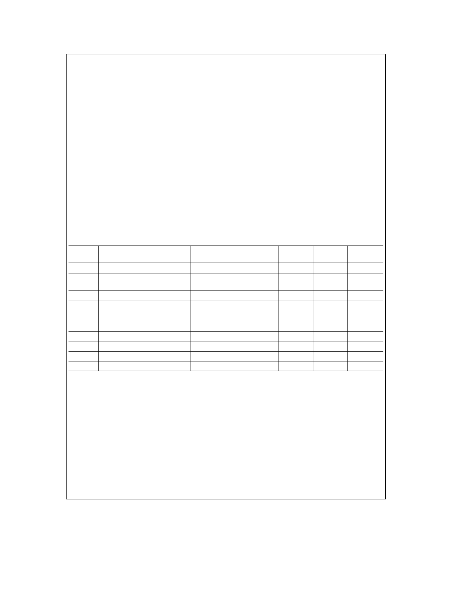
Converter DC Characteristics
The following specifications apply to the ADC12048 for V
A
a
e
V
D
a
e
5V
V
REF
a
e
4 096V V
REF
b
e
0 0V 12-bit a sign conversion mode f
CLK
e
12 0 MHz R
S
e
25X source impedance for V
REF
a
and V
REF
b
s
1X fully differential input with fixed 2 048V common-mode voltage (V
INCM
) and minimum acquisition time unless
otherwise specified Boldface limits apply for T
A
e
T
J
e
T
MIN
to T
MAX
all other limits T
A
e
T
J
e
25 C
Symbol
Parameter
Conditions
Typical
Limits
Unit
(Note 10)
(Note 11)
(Limit)
Resolution with No Missing Codes
After Auto-Cal
13
Bits (max)
ILE
Positive and Negative Integral
After Auto-Cal
g
0 6
g
1
LSB (max)
Linearity Error
(Notes 12 and 17)
DNL
Differential Non-Linearity
After Auto-Cal
g
1
LSB (max)
Zero Error
After Auto-Cal (Notes 13 and 17)
LSB (max)
V
INCM
e
5 0V
g
5 5
V
INCM
e
2 048V
g
2 5
V
INCM
e
0V
g
5 5
Positive Full-Scale Error
After Auto-Cal (Notes 12 and 17)
g
1 0
g
2 5
LSB (max)
Negative Full-Scale Error
After Auto-Cal (Notes 12 and 17)
g
1 0
g
2 5
LSB (max)
DC Common Mode Error
After Auto-Cal (Note 14)
g
2
g
5 5
LSB (max)
TUE
Total Unadjusted Error
After Auto-Cal (Note 18)
g
1
LSB
3