Table 7. ccfl specifications – Rainbow Electronics MAX8709 User Manual
Page 21
MAX8709
High-Efficiency CCFL Backlight
Controller with SMBus Interface
______________________________________________________________________________________
21
The transformer core saturation also needs to be con-
sidered when selecting the operating frequency. The
primary winding should have enough turns to prevent
transformer saturation under all operating conditions.
Use the following expression to calculate the minimum
number of turns (N1) of the primary winding:
where D
MAX
is the maximum duty cycle (approximately
0.8) of the high-side switches, V
IN(MAX)
is the maximum
DC input voltage, B
S
is the saturation flux density of the
core, and S is the minimal cross-section area of the core.
Compensation Design
The CCI capacitor sets the speed of the current loop
that is used during startup, maintaining lamp current
regulation, and during transients caused by changing
the input voltage. The typical CCI value is 0.1µF. Larger
values increase the transient-response delays. Smaller
values speed up transient response, but extremely
small values can cause loop instability.
The CCV capacitor sets the speed of the voltage loop
that affects soft-start and soft-stop during DPWM opera-
tion, and voltage loop stability during startup and open-
lamp conditions. The typical CCV capacitor value is
10nF. Use the smallest value of CCV that gives an
acceptable fault transient response and does not cause
excessive ringing at the beginning of a DPWM pulse.
Larger CCV values reduce transient overshoot but can
reduce light output at low-DPWM duty cycles by increas-
ing the time required to reach the tube strike voltage.
Other Components
The external bootstrap circuits formed by D1 and
C5/C6 in Figure 1 power the high-side MOSFET drivers.
Connect BST1/BST2 through a signal-level silicon
diode to V
DD
, and bypass it to LX1/LX2 with a 0.1µF
ceramic capacitor.
Layout Guidelines
Careful PC board layout is critical to achieve stable
operation. The high-voltage section and the switching
section of the circuit require particular attention. The
high-voltage sections of the layout need to be well sep-
arated from the control circuit. Most layouts for single-
lamp notebook displays are constrained to the long
and narrow form factor, so this separation occurs natu-
rally. Follow these guidelines for good PC board layout:
1)
Keep the high-current paths short and wide, espe-
cially at the ground terminals. This is essential for
stable, jitter-free operation, and high efficiency.
2)
Utilize a star-ground configuration for power and
analog grounds. The power and analog grounds
should be completely isolated—meeting only at the
center of the star. The center should be placed at
the exposed backside pad to the QFN package.
Using separate copper islands for these grounds
may simplify this task. Quiet analog ground is used
for REF, CCV, CCI, and ILIM (if a resistive voltage-
divider is used).
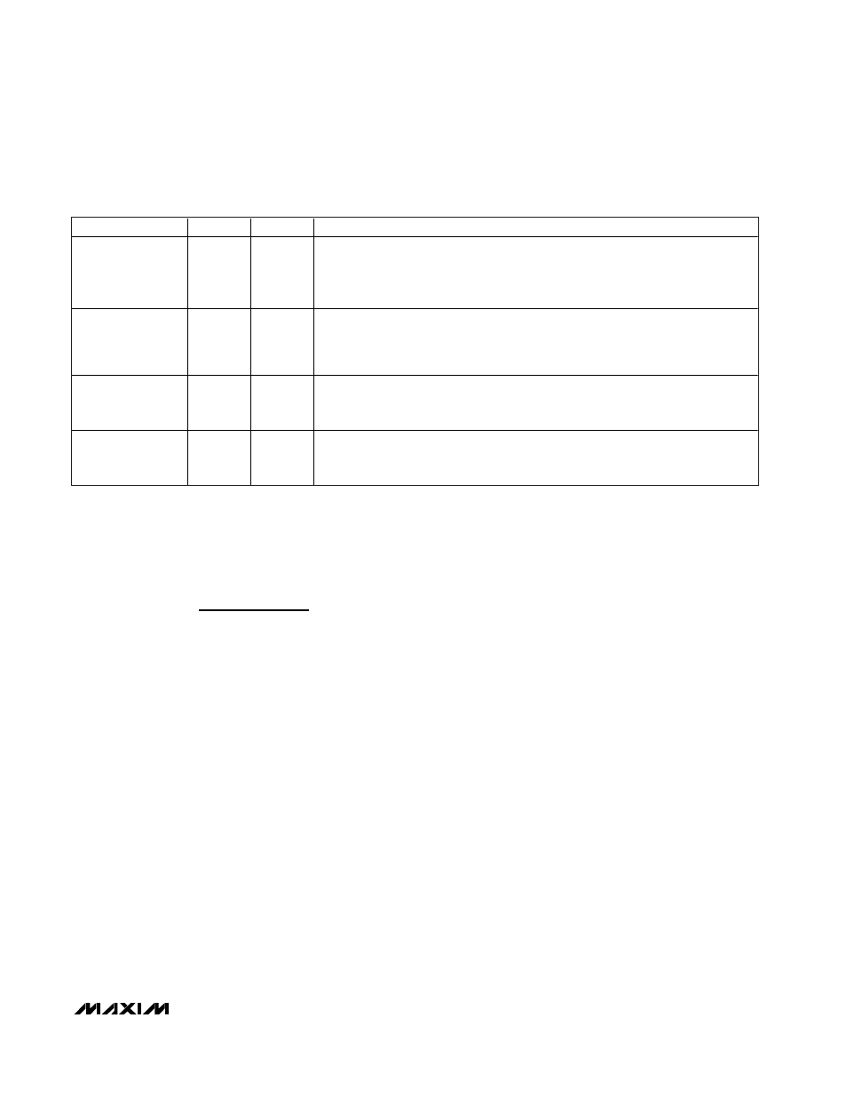
Table 7. CCFL Specifications
SPECIFICATION
SYMBOL
UNITS
DESCRIPTION
CCFL Minimum
Striking Voltage
(Kick-Off Voltage)
V
STRIKE
V
RMS
Although CCFLs typically operate at less than 550V
RMS
, a higher voltage (1000V
RMS
and up) is required initially to start the tube. The strike voltage is typically higher at
cold temperatures and at the end of life of the tube. Resonant operation and the
high Q of the resonant tank generate the required strike voltage of the lamp.
CCFL Typical
Operating Voltage
(Lamp Voltage)
V
LAMP
V
RMS
Once a CCFL has been struck, the lamp voltage required to maintain light output
falls to approximately 550V
RMS
. Short tubes may operate on as little as 250V
RMS
.
The operating voltage of the CCFL stays relatively constant, even as the tube’s
brightness is varied.
CCFL Operating
Current
(Lamp Current)
I
LAMP
mA
RMS
The desired RMS AC current through a CCFL is typically 6mA
RMS
. DC current is not
allowed through CCFLs. The sense resistor, R1, sets the lamp current.
CCFL Maximum
Frequency
(Lamp Frequency)
f
kHz
The maximum AC-lamp-current frequency. The circuit should be designed to
operate the lamp below this frequency. The MAX8709 is designed to operate
between 20kHz and 100kHz.