Rainbow Electronics MAX8709 User Manual
Page 13
MAX8709
High-Efficiency CCFL Backlight
Controller with SMBus Interface
______________________________________________________________________________________
13
ondary leakage inductance, and R
L
is an idealized
resistance that models the CCFL in normal operation.
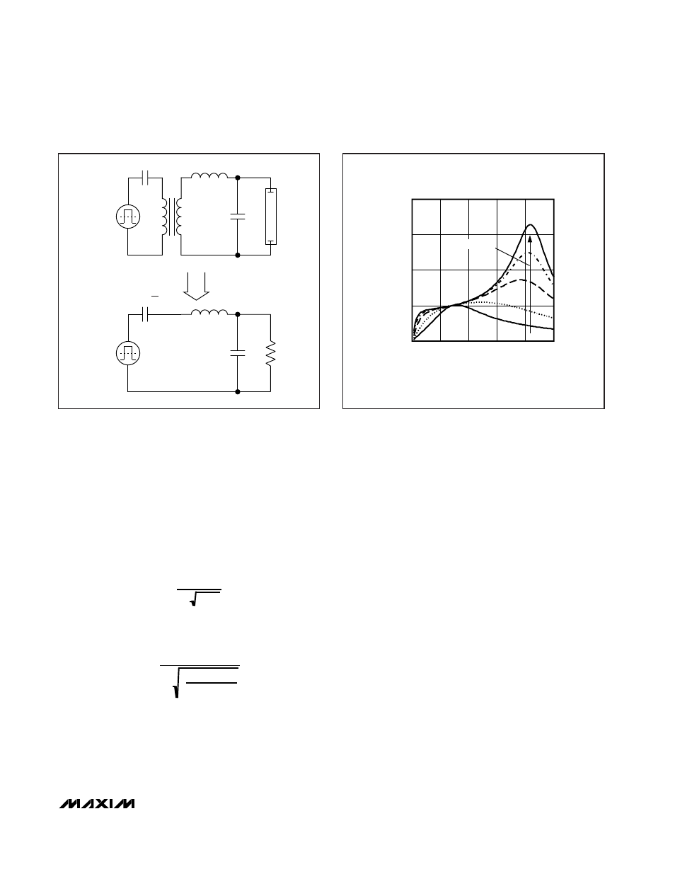
Figure 5 shows the frequency response of the resonant
tank’s voltage gain under different load conditions. The
primary series capacitor is 1µF, the secondary parallel
capacitor is 15pF, the transformer turns ratio is 1:93,
and the secondary leakage inductance is 260mH.
Notice there are two peaks, f
S
and f
P
, in the frequency
response. The first peak, f
S
, is the series resonant peak
determined by the reflected series capacitor and the
secondary leakage inductance:
The second peak, f
P
, is the parallel resonant peak deter-
mined by the reflected series capacitor, the parallel
capacitor, and the secondary leakage inductance:
These two frequencies set the lower and upper bound-
aries of resonant operation. When the lamp is off, the
operating point of the resonant tank is close to the paral-
lel resonant peak due to the infinite lamp impedance.
The circuit displays the characteristics of a parallel-
loaded resonant converter, acting like a voltage source
to generate the necessary striking voltage. Theoretically,
the output voltage of the resonant converter keeps
going until the lamp is ionized.
Once the lamp is ionized, the equivalent load resistance
decreases rapidly and the operating point moves toward
the series resonant peak. The series resonant operation
causes the circuit to behave like a current source.
Current and Voltage Control Loops
(CCI, CCV)
The MAX8709 uses a current loop and a voltage loop to
control the power delivered to the CCFL. The current
loop is the dominant loop in regulating the lamp cur-
rent. The voltage loop limits the transformer secondary
voltage and is active during startup, the DPWM off-
time, and open-lamp fault.
Both the current and the voltage loops use transcon-
ductance error amplifiers for regulation. The AC lamp
current is measured with a sense resistor in series with
the CCFL. The voltage across this resistor is applied to
the IFB input and is internally half-wave rectified. The
current-loop transconductance error amplifier com-
pares the rectified IFB voltage with a 400mV internal
threshold to create an error current. The error current
charges and discharges a capacitor connected
between CCI and ground to generate an error voltage
V
CCI
. Similarly, the AC voltage across the transformer
secondary winding is measured through a capacitive
voltage-divider. The sense voltage is applied to the
VFB input and is internally half-wave rectified. The volt-
f
P
=
1
2π L
C'
S
C
P
C'
S
+ C
P
f
S
=
1
2π L C'
S
AC
SOURCE
CCFL
C
P
L
C
S
1:N
(a)
AC
SOURCE
R
L
C
P
L
C'
S
=
(b)
C
S
N
2
Figure 4. Equivalent Resonant Tank Circuit
FREQUENCY (kHz)
VOLTAGE GAIN (V/V)
80
60
40
20
1
2
3
4
0
0
100
R
L
INCREASING
Figure 5. Frequency Response of the Resonant Tank