Rainbow Electronics MAX8709 User Manual
Page 12
MAX8709
High-Efficiency CCFL Backlight
Controller with SMBus Interface
12
______________________________________________________________________________________
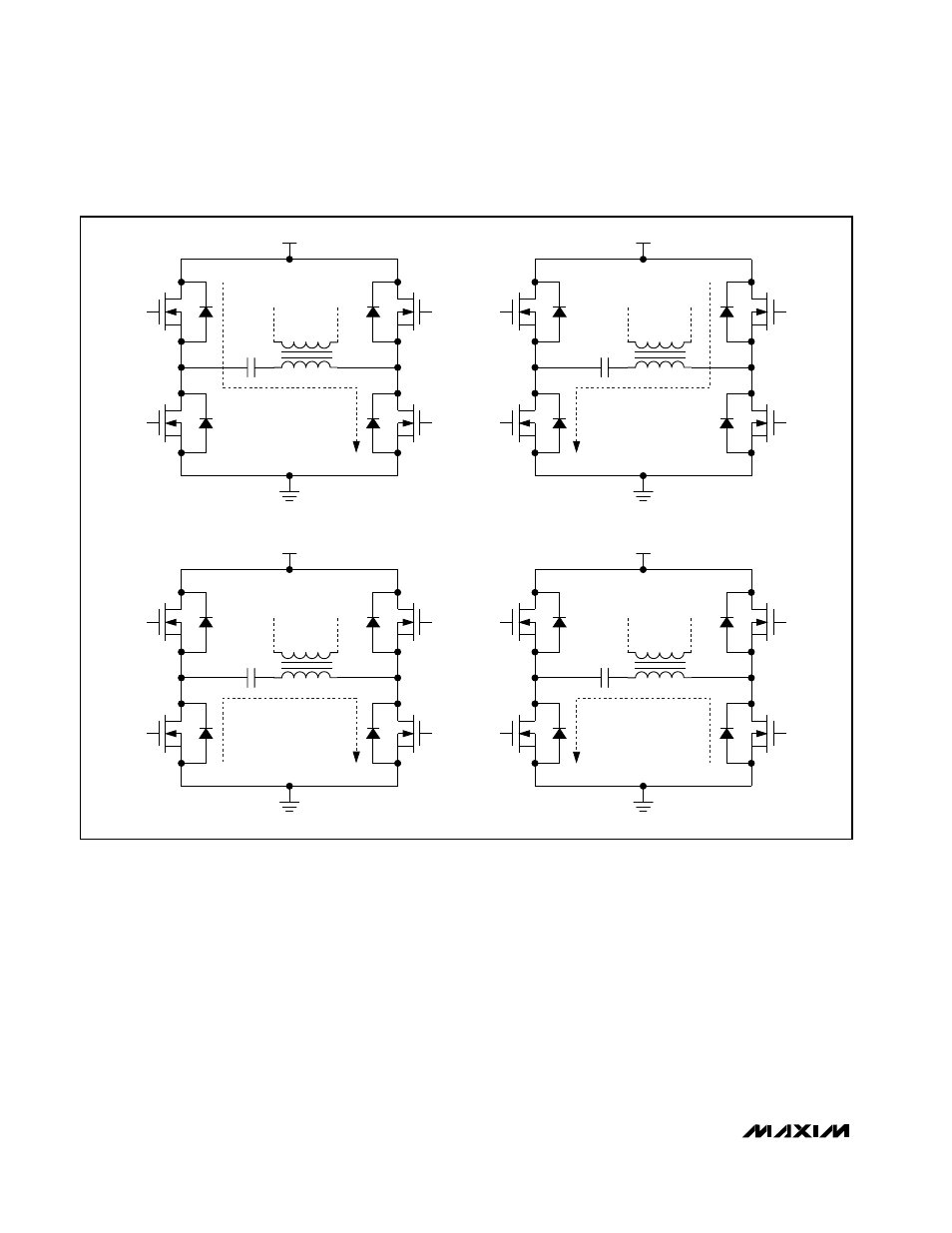
body diode of NH2 is forward biased.
When NH2 turns on, it does so with near-zero drain-to-
source voltage. The primary current reverses polarity as
shown in Figure 3(c), beginning a new cycle with the cur-
rent flowing in the opposite direction, with NH2 and NL1
on. The primary current ramps up until the controller turns
off NH2. When NH2 turns off, the primary current forward
biases the body diode of NL2, which clamps the LX2 volt-
age just below ground as shown in Figure 3(d). After the
LX2 node goes low, the controller losslessly turns on NL2.
Once the primary current drops to the minimum current
threshold, the controller turns off NL1. The remaining
energy charges up the LX1 node until the body diode of
NH1 is forward biased. Finally, NH1 losslessly turns on,
beginning a new cycle as shown in Figure 3(a). Note that
switching transitions on all four power MOSFETs occur
under ZVS conditions, which reduce transient power loss-
es and EMI.
The simplified CCFL inverter circuit is shown in Figure
4(a). The full-bridge power stage is simplified and rep-
resented as a square-wave AC source. The resonant
tank circuit can be further simplified to Figure 4(b) by
removing the transformer. C
S
is the primary series
capacitor, C’
S
is the series capacitance reflected to the
secondary, C
P
is the secondary parallel capacitor, N is
the transformer turns ratio, L is the transformer sec-
T1
C2
VBATT
(a)
NH1
ON
NL1
OFF
NH2
OFF
NL2
ON
LX2
LX1
T1
C2
VBATT
(b)
NH1
OFF
NL1
ON
NH2
OFF
NL2
ON
LX2
LX1
T1
C2
VBATT
(c)
NH1
OFF
NL1
ON
NH2
ON
NL2
OFF
LX2
LX1
T1
C2
VBATT
(d)
NH1
OFF
NL1
ON
NH2
OFF
NL2
ON
LX2
LX1
(BODY DIODE TURNS ON FIRST)
(BODY DIODE TURNS ON FIRST)
Figure 3. Resonant Operation