Applications information, Table 5. sus and shmd register truth table – Rainbow Electronics MAX8709 User Manual
Page 19
MAX8709
High-Efficiency CCFL Backlight
Controller with SMBus Interface
______________________________________________________________________________________
19
Status Register [STATUS1–STATUS0]
(POR = 0b11)
The status register returns information on fault condi-
tions. If the MAX8709 detects that V
IFB
does not
exceed 30% of V
LOT
continuously for 1.22s, the IC
latches STATUS1 to zero. STATUS1 is reset to 1 by tog-
gling SUS or by toggling the input power.
STATUS0 reports 1 as long as no overcurrent condi-
tions are detected. If an overcurrent condition is detect-
ed in any given digital PWM period, STATUS0 is
cleared for the duration of the following digital PWM
period. If an overcurrent condition is not detected in
any given digital PWM period, STATUS0 is set for the
duration of the following digital PWM period. Note that
the status-register polarity of command bytes 0xA9 and
0xAA are inverted from that of command byte 0x02.
ID Registers
The ID registers return information on the manufacturer
chip ID and the chip revision number. The MAX8709 is
the first-generation advanced CCFL controller and its
ChipRev is 0x00. Reading from MfgID register returns
0x4D, which is the ASCII code for M (for Maxim). The
ChipID register returns 0x0D. Writing to these registers
has no effect.
Applications Information
To select the correct component values for the MAX8709,
several CCFL parameters must be specified. (Table 7)
MOSFETs
The MAX8709 requires four external N-channel power
MOSFETs (NL1, NL2, NH1, and NH2) to form a full-bridge
inverter circuit to drive the transformer primary. The regu-
lator senses the on-state drain-to-source voltage of the
two low-side MOSFETs NL1 and NL2 to detect the trans-
former primary current, so the R
DS(ON)
of NL1 and NL2
should be matched. For instance, if dual MOSFETs are
used to form the full bridge, NL1 and NL2 should be in
one package. Select dual logic-level N-channel MOSFETs
with low R
DS(ON)
to minimize conduction loss for
NL1/NL2 and NH1/NH2. The regulator utilizes the energy
stored in the transformer’s primary leakage inductance to
softly turn on each of four switches in the full bridge zero
voltage switching (ZVS) occurs when the external power
MOSFETs are turned on when their respective drain-to-
source voltages are near 0V. ZVS effectively eliminates
the instantaneous turn-on loss of MOSFETs caused by
C
OSS
(drain-to-source capacitance) and parasitic capac-
itance discharge, and improves efficiency and reduces
switching-related EMI.
Setting the Lamp Current
The MAX8709 senses the lamp current flowing through
a resistor R1 (Figure 1) connected between the low-
voltage terminal of the lamp and ground. The voltage
across R1 is fed to IFB and is internally rectified. The
MAX8709 controls the desired lamp current by regulat-
ing the average of the half-wave rectified IFB voltage.
To set the RMS lamp current, determine R1 as follows:
where I
LAMP(RMS)
is the desired RMS lamp current and
400mV is the typical value of the IFB regulation point
specified in the Electrical Characteristics table.
R
mV
I
LAMP RMS
1
400
2
=
Ч
Ч
π
(
)
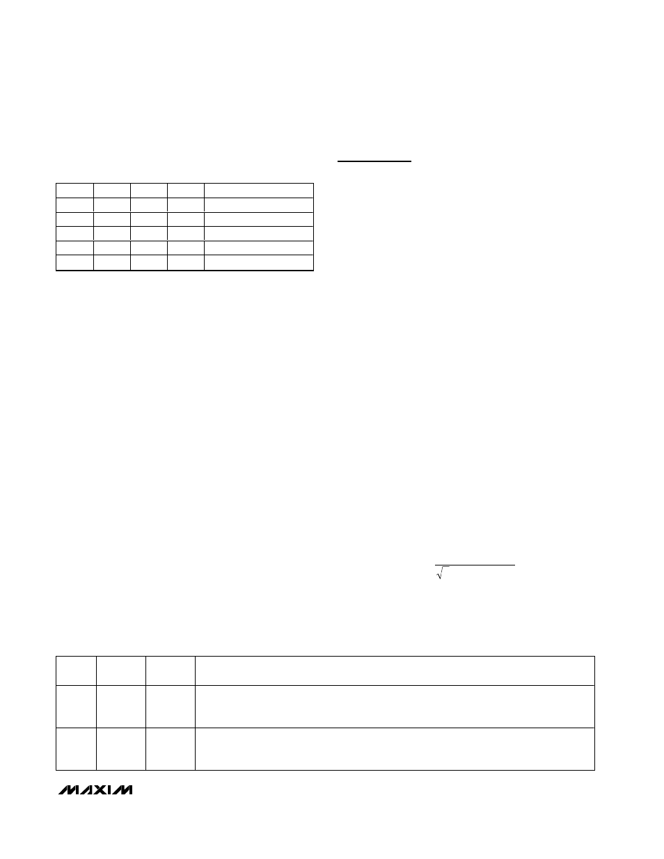
Table 5. SUS and SHMD Register Truth
Table
SUS
SHMD2 SHMD1 SHMD0
OPERATING MODE
0
0
X
0
Operate
0
0
X
1
Shutdown, STATUS1 set
1
0
0
X
Operate
1
0
1
X
Shutdown, STATUS1 set
X
1
X
X
Shutdown, STATUS1 set
X = Don’t care.
Table 6. Status-Register Bit Descriptions (Read Only, Writes Have No Effect)
BIT
NAME
POR
STATE
DESCRIPTION
1
STATUS1
1
STATUS1 = 0 (or STATUS1 = 1) means that a lamp-out condition has been detected. The
STATUS1 bit stays clear even after the lamp-out condition has gone away. The only way to set
STATUS1 is to shut off the lamp by programming the shutdown-mode register or by toggling SUS.
0
STATUS0
1
STATUS0 = 0 (or STATUS0 = 1) means that an overcurrent condition was detected during the
previous digital PWM period. STATUS0 = 1 means that an overcurrent condition was not detected
during the previous digital PWM period.