Max9867 ultra-low power stereo audio codec, Table 14. adc input register – Rainbow Electronics MAX9867 User Manual
Page 41
MAX9867
Ultra-Low Power Stereo Audio Codec
______________________________________________________________________________________
41
Complete DC Measurement Example
MCLK = 13MHz, slave mode, BCLK and LRCLK not
externally supplied:
1) Configure the digital audio interface for f
S
= 48kHz
(PSCLK = 01, FREQ = 0x0, PLL = 0, NI = 0x5ABE,
MAS = 0).
2) Disable JACKSNS (JDETEN = 0).
3) Enable the left and right ADC; take the MAX9867 out
of shutdown (ADLEN = ADREN = SHDN = 1).
4) Calibrate the offset:
a. Enable the AUX input (AUXEN = 1).
b. Enable the offset calibration (AUXCAL = 1).
c. Wait 40ms.
d. Complete calibration (AUXCAL = 0).
5) Calibrate the gain:
a. Start gain calibration (AUXGAIN = 1).
b. Wait 40ms.
c. Freeze the measurement results (AUXCAP = 1).
d. Read AUX and store the value in memory to cor-
rect all future measurements (k = (AUX[15:0]).
e. Complete calibration (AUXGAIN = AUXCAP =
AUXEN = 0).
6) Measure the voltage on JACKSNS/AUX:
a. Enable the AUX input (AUXEN = 1).
b. Wait 40ms.
c. Freeze the measurement results (AUXCAP = 1).
d. Read AUX and correct with the gain calibration
value.
e. Complete measurement (AUXCAP = 0).
7) DC measurement complete.
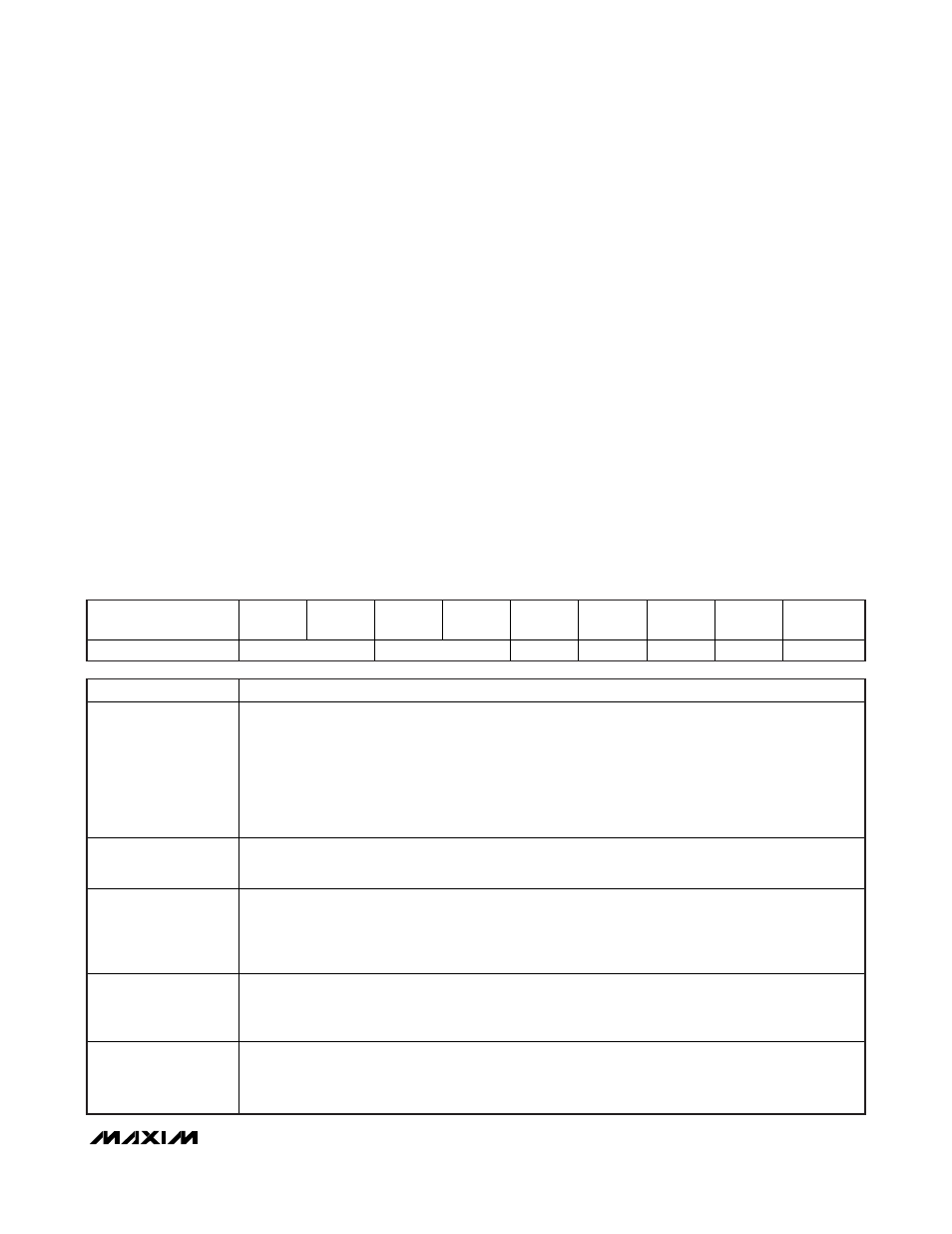
Table 14. ADC Input Register
REGISTER
B7
B6
B5
B4
B3
B2
B1
B0
REGISTER
ADDRESS
ADC Input
MXINL
MXINR
AUXCAP
AU X GAIN AUXCAL
AUXEN
0x14
BITS
FUNCTION
MXINL/MXINR
Left/Right ADC Audio Input Mixer
00 = No input is selected.
01 = Left/right analog microphone
10 = Left/right line input
11 = Left/right analog microphone + line input
Note: If the right-line input is disabled, then the left-line input is connected to both mixers. Enabling the
left and right digital microphones disables the left and right audio mixers, respectively. See DIGMICL/
DIGMICR in Table 15 for more details.
AUXCAP
Auxiliary Input Capture
0 = Update AUX with the voltage at JACKSNS/AUX.
1 = Hold AUX for reading.
AUXGAIN
Auxiliary Input Gain Calibration
0 = Normal operation
1 = The input buffer is disconnected from JACKSNS/AUX and connected to an internal voltage reference.
While in this mode, read the AUX register and store the value. Use the stored value as a gain
calibration factor, K, on subsequent readings.
AUXCAL
Auxiliary Input Offset Calibration
0 = Normal operation
1 = JACKSNS/AUX is disconnected from the input and the ADC automatically calibrates out any internal
offsets.
AUXEN
Auxiliary Input Enable
0 = Use JACKSNS/AUX for jack detection.
1 = Use JACKSNS/AUX for DC measurements.
Note: For AUXEN = 1, set MXINR = 00, ADLEN = 1, and ADREN = 1.