Typical operating characteristics, Electrical characteristics (continued) – Rainbow Electronics MAX5945 User Manual
Page 6
MAX5945
Quad Network Power Controller
for Power-Over-LAN
6
_______________________________________________________________________________________
Note 2: Default values. The charge/discharge currents are programmable through the serial interface (see the Register Map and
Description section).
Note 3: Default values. The current-limit thresholds are programmed through the I
2
C-compatible serial interface (see the Register
Map and Description section).
Note 4: This is the default value. Threshold can be programmed through serial interface R23h[2:0].
Note 5: AC disconnect works only if V
DD
- V
DGND
≥ 3V.
Note 6: t
DISC
can also be programmed through the serial interface (R29h) (see the Register Map and Description section).
Note 7: R
D
= (V
OUT_2
- V
OUT_1
) / (I
DET_2
- I
DET_1
). V
OUT_1
, V
OUT_2
, I
DET_2
and I
DET_1
represent the voltage at OUT_ and the current
at DET_ during phase 1 and 2 of the detection.
Note 8: Default values. The startup and fault times can also be programmed through the I
2
C serial interface (see the Register Map
and Description section).
Note 9: Guaranteed by design. Not subject to production testing.
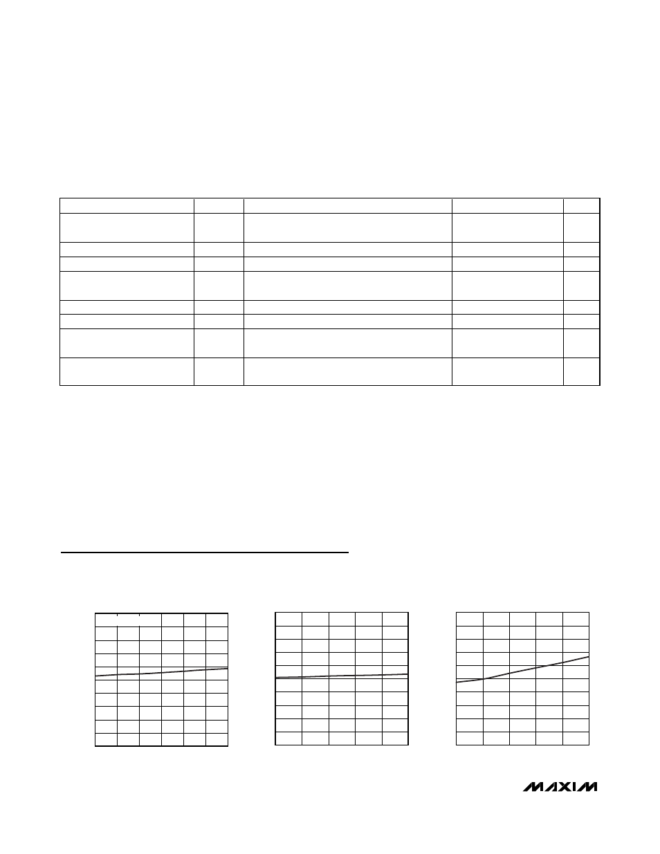
ANALOG SUPPLY CURRENT
vs. INPUT VOLTAGE
MAX5945 toc01
INPUT VOLTAGE (V)
SUPPLY CURRENT (mA)
57
52
47
42
37
3.6
3.7
3.8
3.9
4.0
4.1
4.2
4.3
4.4
4.5
3.5
32
62
MEASURED AT AGND
ANALOG SUPPLY CURRENT
vs. TEMPERATURE
MAX5945 toc02
TEMPERATURE (
°C)
SUPPLY CURRENT (mA)
60
35
10
-15
3.2
3.4
3.6
3.8
4.0
4.2
4.4
4.6
4.8
5.0
3.0
-40
85
DIGITAL SUPPLY CURRENT
vs. TEMPERATURE
MAX5945 toc03
TEMPERATURE (
°C)
SUPPLY CURRENT (mA)
60
35
10
-15
0.5
1.0
1.5
2.0
2.5
3.0
3.5
4.0
4.5
5.0
0
-40
85
Typical Operating Characteristics
(V
EE
= -48V, V
DD
= +3.3V, AUTO = AGND = DGND = 0V, RESET = SHD_ = unconnected, R
SENSE
= 0.5
Ω, all registers = default setting,
T
A
= +25°C, unless otherwise noted.)
ELECTRICAL CHARACTERISTICS (continued)
(AGND = +32V to +60V, V
EE
= 0V, V
DD
to DGND = +3.3V, all voltages are referenced to V
EE
, unless otherwise noted. Typical
values are at AGND = +48V, DGND = +48V, V
DD
= (DGND + 3.3V), T
A
= +25°C. Currents are positive when entering the pin and
negative otherwise.)
PARAMETER
SYMBOL
CONDITIONS
MIN
TYP
MAX
UNITS
Setup Time for a Repeated
START Condition (Sr)
t
SU, STA
(Note 9)
0.6
µs
Data Hold Time
t
HD, DAT
(Note 9)
0
150
ns
Data Setup Time
t
SU, DAT
(Note 9)
100
ns
Rise Time of Both SDA and
SCL Signals, Receiving
t
R
(Note 9)
20 + 0.1C
B
300
ns
Fall Time of SDA Transmitting
t
F
(Note 9)
20 + 0.1C
B
300
ns
Setup Time for STOP Condition
t
SU, STO
(Note 9)
0.6
µs
C ap aci ti ve Load for E ach Bus
Li ne
C
B
(Note 9)
400
pF
Pulse Width of Spike
Suppressed
t
SP
(Note 9)
50
ns