Rainbow Electronics MAX5945 User Manual
Page 15
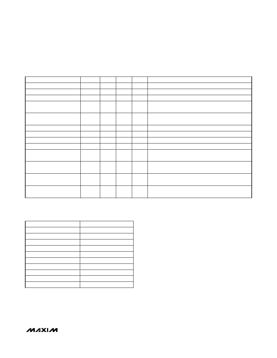
Table 2 shows the IEEE 802.3af requirement for a PSE
classifying a PD at the power interface (PI).
Powered State
When the part enters PWR MODE, the t
START
and t
DISC
timers are reset. Before turning on the power, the part
checks if any other port is not turning on and if the
t
FAULT
timer is zero. Another check is performed if the
ACD_EN bit is set, in this case OSC_FAIL bit must be
low (oscillator is okay) for the port to be powered.
If these conditions are met then the part enters startup
where it turns on power to the port. An internal signal,
POK_, is asserted high when V
OUT
is within 2V from
V
EE
. PGOOD_ status bits are set high if POK_ stays
high longer than t
PGOOD
. PGOOD immediately resets
when POK goes low.
The PWR_CHG bit sets when a port powers up or down.
PWR_EN sets when a port powers up and resets when a
port shuts down. The port shutdown timer lasts 0.5ms
and prevents other ports from turning off during that peri-
od, except in the case of emergency shutdowns (RESET
= L, RESET_IC = H, V
EEUVLO
, V
DDUVLO
, and TSHD).
The MAX5945 always checks the status of all ports before
turning off. A priority logic system determines the order to
prevent the simultaneous turn-on or turn-off of the ports.
The port with the lesser ordinal number gets priority over
the others (i.e., port 1 turns on first, port 2 second, port 3
third and port 4 fourth). Setting PWR_OFF_ high turns off
power to the corresponding port.
MAX5945
Quad Network Power Controller
for Power-Over-LAN
______________________________________________________________________________________
15
PARAMETER
SYMBOL
MIN
MAX
UNITS
ADDITIONAL INFORMATION
Open-Circuit Voltage
V
OC
—
30
V
In detection mode only
Short-Circuit Current
I
SC
—
5
mA
In detection mode only
Valid Test Voltage
V
VALID
2.8
10
V
Voltage Difference Between
Test Points
∆V
TEST
1
—
V
Time Between Any Two Test
Points
t
BP
2
—
ms
This timing implies a 500Hz maximum probing frequency
Slew Rate
V
SLEW
—
0.1
V/µs
Accept Signature Resistance
R
GOOD
19
26.5
k
Ω
Reject Signature Resistance
R
BAD
< 15
> 33
k
Ω
Open-Circuit Resistance
R
OPEN
500
—
k
Ω
Accept Signature
Capacitance
C
GOOD
—
150
nF
Reject Signature
Capacitance
C
BAD
10
—
µF
Signature Offset Voltage
Tolerance
V
OS
0
2.0
V
Signature Offset Current
Tolerance
I
OS
0
12
µA
Table 1. PSE PI Detection Modes Electrical Requirement
(Table 33-2 of the IEEE 802.3af Standard)
MEASURED I
CLASS
(mA)
CLASSIFICATION
0 to 5
Class 0
> 5 and < 8
May be Class 0 and 1
8 to 13
Class 1
> 13 and < 16
May be Class 0, 1, or 2
16 to 21
Class 2
> 21 and < 25
May be Class 0, 2, or 3
25 to 31
Class 3
> 31 and <35
May be Class 0, 3, or 4
35 to 45
Class 4
> 45 and < 51
May be Class 0 or 4
Table 2. PSE Classification of a PD
(Table 33-4 of the IEEE 802.3af Standard)