Electrical characteristics (continued) – Rainbow Electronics MAX5945 User Manual
Page 5
MAX5945
Quad Network Power Controller
for Power-Over-LAN
_______________________________________________________________________________________
5
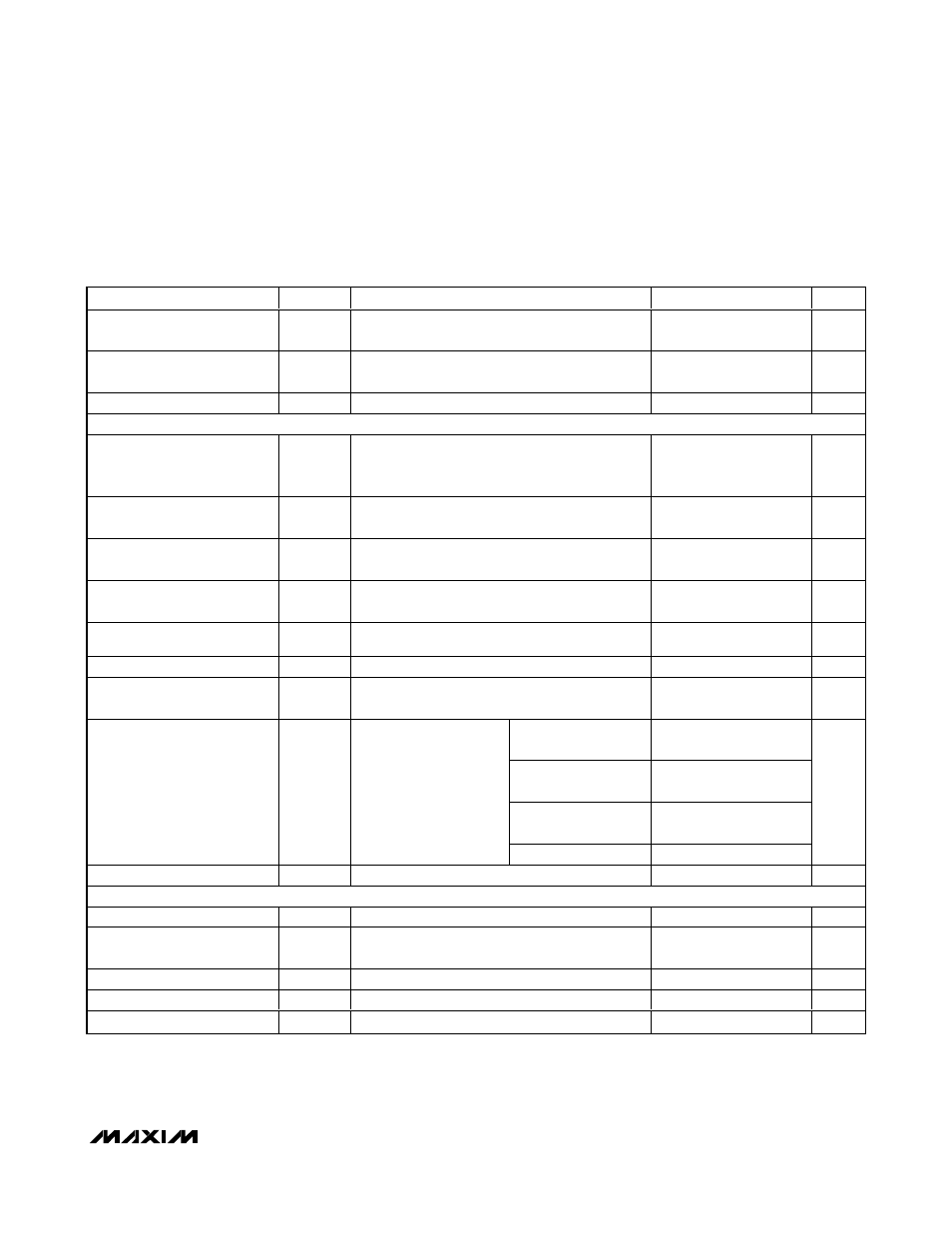
ELECTRICAL CHARACTERISTICS (continued)
(AGND = +32V to +60V, V
EE
= 0V, V
DD
to DGND = +3.3V, all voltages are referenced to V
EE
, unless otherwise noted. Typical
values are at AGND = +48V, DGND = +48V, V
DD
= (DGND + 3.3V), T
A
= +25°C. Currents are positive when entering the pin and
negative otherwise.)
PARAMETER
SYMBOL
CONDITIONS
MIN
TYP
MAX
UNITS
Internal Input Pullup/Pulldown
Resistor
R
DIN
Pullup (pulldown) resistor to V
DD
(DGND) to set
default level
25
50
75
k
Ω
Open-Drain Output Low
Voltage
V
OL
I
SINK
= 15mA
0.4
V
Open-Drain Leakage
I
OL
Open-drain high impedance, V
O
= 3.3V
2
µA
TIMING
Startup Time
t
START
Time during which a current limit set by V
SU_LIM
is allowed, starts when the GATE_
is turned on (Note 8)
50
60
70
ms
Fault Time
t
FAULT
Maximum allowed time for an overcurrent
condition set by V
FLT_LIM
after startup (Note 8)
50
60
70
ms
Port Turn-Off Time
t
OFF
Minimum delay between any port turning off,
does not apply in the case of a reset
0.5
0.75
1.0
ms
Detection Time
t
DET
Maximum time allowed before detection
is completed
320
ms
Midspan Mode Detection
Delay
t
DMID
2.0
2.4
s
Classification Time
t
CLASS
Time allowed for classification
40
ms
V
EEUVLO
Turn-On Delay
t
DLY
Time V
AGND
must be above the V
EEUVLO
thresholds before the device operates
2
4
ms
RSTR bits = 00
16 x
t
FAULT
RSTR bits = 01
32 x
t
FAULT
RSTR bits = 10
64 x
t
FAULT
Restart Timer
t
RESTART
Ti m e a p or t has to w ai t
b efor e tur ni ng on after an
over cur r ent faul t,
RS TR_E N b i t = hi g h
RSTR bits = 11
0
ms
Watchdog Clock Period
t
WD
Rate of decrement of the watchdog timer
164
ms
TIMING CHARACTERISTICS for 2-WIRE FAST MODE (Figures 5 and 6)
Serial Clock Frequency
f
SCL
(Note 9)
400
kHz
Bus Free Time Between a
STOP and a START Condition
t
BUF
(Note 9)
1.2
µs
Hold Time for Start Condition
t
HD, STA
(Note 9)
0.6
µs
Low Period of the SCL Clock
t
LOW
(Note 9)
1.2
µs
High Period of the SCL Clock
t
HIGH
(Note 9)
0.6
µs