Table 23. id register, Table 24. smode register – Rainbow Electronics MAX5945 User Manual
Page 31
Writing a 1 to CLR_INT (Table 22) clears all the event
registers and the corresponding interrupt bits in register
R00h. Writing a 1 to RESET_P_ turns off power to the cor-
responding port and resets only the status and event
registers of that port. After execution, the bits reset to 0.
Writing a 1 to RESET_IC causes a global software reset,
after which the register map is set back to its reset state.
A reset sets R1Ah = 00h.
Enable SMODE function (Table 24) by setting
EN_WHDOG (R1Fh[7]) to 1. SMODE_ bit goes high when
the watchdog counter reaches zero and the port(s)
switch over to hardware-controlled mode. SMODE_ also
goes high each and every time the software tries to
power-on a port but is denied since the port is in hard-
ware mode. A reset sets R1Ch = 00h.
Set EN_WHDOG (R1Fh[7]) to 1 (Table 25) to enable the
watchdog function. When activated, the watchdog timer
counter, WDTIME[7:0], continuously decrements toward
zero once every 164ms. Once the counter reaches zero
(also called watchdog expiry), the MAX5945 enters hard-
ware-controlled mode and each port shifts to a mode set
by the HWMODE_ bit in register R1Fh (Table 24). Use
software to set WDTIME and continuously set this register
to some non-zero value before the register reaches zero
to prevent a watchdog expiry. In this way, the software
gracefully manages the power to ports upon a system
crash or switchover.
While in hardware-controlled mode, the MAX5945
ignores all requests to turn the power on and the flag
SMODE_ indicates that the hardware took control of the
MAX5945 operation. In addition, the software is not
allowed to change the mode of operation in hardware-
controlled mode. A reset sets R1Eh = 00h.
Setting EN_WHDOG (Table 26) high activates the
watchdog counter. When the counter reaches zero, the
port switches to the hardware-controlled mode deter-
mined by the corresponding HWMODE_ bit. A low in
HWMODE_ switches the port into shutdown by setting
MAX5945
Quad Network Power Controller
for Power-Over-LAN
______________________________________________________________________________________
31
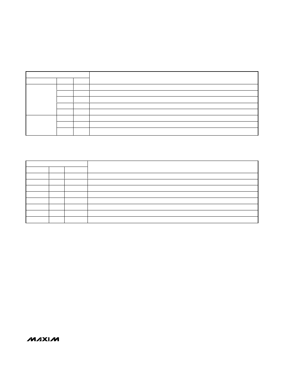
ADDRESS = 1Bh
SYMBOL
BIT
R/W
DESCRIPTION
7
R
ID_CODE[4]
6
R
ID_CODE[3]
5
R
ID_CODE[2]
4
R
ID_CODE[1]
ID_CODE
3
R
ID_CODE[0]
2
R
REV [2]
1
R
REV [1]
REV
0
R
REV [0]
Table 23. ID Register
ID register keeps track of the device ID number and revision. The MAX5945’s ID_CODE[4:0] = 11000b. Contact the factory for
REV[2:0] value.
ADDRESS = 1Ch
SYMBOL
BIT
CoR
DESCRIPTION
Reserved
7
—
Reserved
Reserved
6
—
Reserved
Reserved
5
—
Reserved
Reserved
4
—
Reserved
SMODE4
3
CoR
Hardware control flag for port 4
SMODE3
2
CoR
Hardware control flag for port 3
SMODE2
1
CoR
Hardware control flag for port 2
SMODE1
0
CoR
Hardware control flag for port 1
Table 24. SMODE Register