Rainbow Electronics MAX5945 User Manual
Page 17
MOSFET Gate Driver
Connect the gate of the external n-channel MOSFET to
GATE_. An internal 50µA current source pulls GATE_ to
(V
EE
+ 10V) to turn on the MOSFET. An internal 40µA
current source pulls down GATE_ to V
EE
to turn off the
MOSFET.
The pullup and pulldown current controls the maximum
slew rate at the output during turn-on or turn-off. The
pullup current (gate-charging current) is programmable
using R23h[5-7]. Use the following equation to set the
maximum slew rate:
where C
GD
is the total capacitance between GATE and
DRAIN of the external FET. Current limit and the capac-
itive load at the drain control the slew rate during start-
up. During current-limit regulation, the MAX5945
manipulates the GATE_ voltage to control the voltage at
SENSE_. A fast pulldown activates if SENSE_ over-
shoots the limit threshold. The fast pulldown current
increases with the amount of overshoot. The maximum
fast pulldown current is 100mA.
During turn-off, when the GATE voltage reaches a value
lower than 1.2V, a strong pulldown switch is activated
to keep the FET securely off.
Digital Logic
V
DD
supplies power for the internal logic circuitry. V
DD
ranges from +1.71V to +3.7V and determines the logic
thresholds for the CMOS connections (SDAIN,
SDAOUT, SCL, AUTO, SHD_, A_). This voltage range
enables the MAX5945 to interface with a nonisolated
low-voltage microcontroller. The MAX5945 checks the
digital supply for compatibility with the internal logic.
The MAX5945 also features a V
DD
undervoltage lockout
(V
DDUVLO
) of +1.35V. A V
DDUVLO
condition keeps the
MAX5945 in reset and the ports shut off. Bit 0 in the
supply event register shows the status of V
DDUVLO
(Table 11) after V
DD
has recovered. All logic inputs and
outputs reference to DGND. DGND and AGND are
completely isolated internally to the MAX5945. In a
completely isolated system, the digital signal can be
referenced indifferently to V
AGND
or V
EE
or at voltages
even higher than AGND (up to 60V). V
DD
- V
DGND
must
be greater than 3.0V when V
DGND
≤ (V
EE
+ 3.0V)
When using the AC disconnect detection feature,
AGND must be connected directly to DGND and V
DD
must be greater than +3V. In this configuration, con-
nect DGND to AGND at a single point in the system as
close to MAX5945 as possible.
Hardware Shutdown
SHD_ shuts down the respective ports without using
the serial interface. Hardware shutdown offers an emer-
gency turn-off feature that allows a fast disconnect of
the power supply from the port. Pull SHD_ low to
remove power.
Interrupt
The MAX5945 contains an open-drain logic output (INT)
that goes low when an interrupt condition exists. R00h
and R01h (Tables 5 and 6) contain the definitions of the
interrupt registers. The mask register R01h determines
events that trigger an interrupt. As a response to an
interrupt, the controller reads the status of the event reg-
ister to determine the cause of the interrupt and takes
subsequent actions. Each interrupt event register also
contains a clear-on-read (CoR) register. Reading
through the CoR register address clears the interrupt.
INT remains low when reading the interrupt through the
read-only addresses. For example, to clear a startup
fault on port 4 read address 09h (see Table 10). Use the
global pushbutton bit on register 1Ah (bit 7, Table 22) to
clear interrupts, or use a software or hardware reset.
Undervoltage and Overvoltage Protection
The MAX5945 contains several undervoltage and over-
voltage protection features. Table 11 in the Register Map
and Description section shows a detailed list of the
undervoltage and overvoltage protection features. An
internal V
EE
undervoltage lockout (V
EEUVLO
) circuit
keeps the MOSFET off and the MAX5945 in reset until
V
AGND
- V
EE
exceeds 29V for more than 3ms. An internal
V
EE
overvoltage (V
EE_OV
) circuit shuts down the ports
when (V
AGND
- V
EE
) exceeds 60V. The digital supply also
contains an undervoltage lockout (V
DDUVLO
).
∆
∆
V
t
I
C
OUT
GATE
GD
=
MAX5945
Quad Network Power Controller
for Power-Over-LAN
______________________________________________________________________________________
17
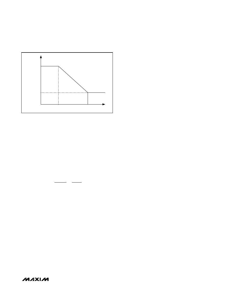
Figure 4. Foldback Current Characteristics
50V
30V
V
SU_LIM
V
SU_LIM
/ 3
(V
SENSE_
- V
EE
)
(V
OUT_
- V
EE
)