Rainbow Electronics MAX5066 User Manual
Page 14
MAX5066
Configurable, Single-/Dual-Output, Synchronous
Buck Controller for High-Current Applications
14
______________________________________________________________________________________
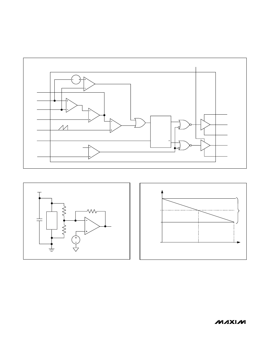
bility of these drivers provides ample drive for the fast
rise and fall times of the switching MOSFETs. Faster rise
and fall times result in reduced switching losses. For low-
output, voltage-regulating applications where the duty
cycle is less than 50%, choose high-side MOSFETs (Q2
and Q4, Figure 6) with a moderate R
DS(ON)
and a very
low gate charge. Choose low-side MOSFETs (Q1 and
Q3, Figure 6) with very low R
DS(ON)
and moderate gate
charge. The driver block also includes a logic circuit that
provides an adaptive nonoverlap time (30ns typical) to
prevent shoot-through currents during transition. Figure 7
shows the dual-phase, single-output buck regulator.
2 x f
SW
(V/S)
RAMP
CLK
CSP_
CSN_
GM
IN
EN_
1.225V
CLP_
V
DD
BST_
DH_
LX_
DL_
PGND
A
V
= 36
PWM
COMPARATOR
PEAK-CURRENT
COMPARATOR
52.5mV
S
R
Q
Q
g
M
= 500
µS
Figure 3. Current Comparator and MOSFET Driver Logic
LOAD
C
OUT
V
OUT
V
REF
= 0.61V
R
F
R
1
R
2
EAN_
EAOUT_
Figure 4. Voltage Error Amplifier
LOAD (A)
V
CNTR
NO LOAD
1/2 LOAD
FULL LOAD
VOL
TAGE-POSITIONING WINDOW
V
CNTR
+
∆V
OUT
/2
V
CNTR
-
∆V
OUT
/2
Figure 5. Defining the Voltage-Positioning Window