Design procedure, Table 3. vendor ids, Table 4. component list – Rainbow Electronics MAX17061 User Manual
Page 19: Table 5. component suppliers
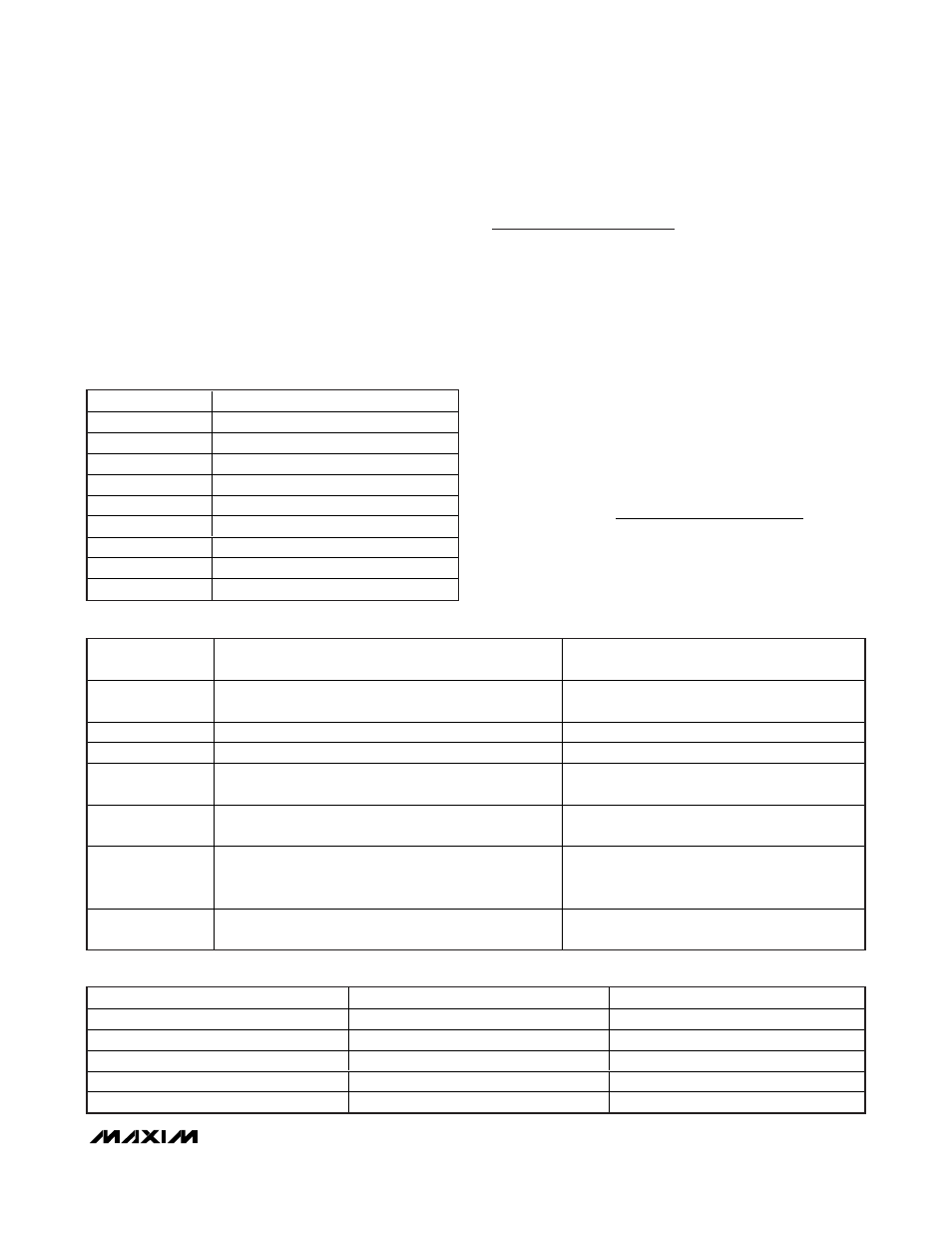
The list of ID values for vendors is shown in Table 3.
Thermal Shutdown
The MAX17061 includes a thermal-protection circuit.
When the local IC temperature exceeds +160°C (typ),
the controller and current sources shut down and do
not restart until the die temperature drops by 15°C.
When thermal shutdown occurs, Bit 1 of fault/status
register is set to 1.
Design Procedure
All MAX17061 designs should be prototyped and test-
ed prior to production. Table 4 provides a list of power
components for the typical applications circuit. Table 5
lists component suppliers.
External component value choice is primarily dictated
by the output voltage and the maximum load current,
as well as maximum and minimum input voltages.
Begin by selecting an inductor value. Once L is known,
choose the diode and capacitors.
Step-Up Converter Current Calculation
At light loads, the MAX17061 automatically skips pulses
to improve efficiency and prevent overcharging the output
capacitor. The output current for the converter SKIP oper-
ation can be calculated by the following equation:
where I
O(SKIP)
is the output current in SKIP mode, V
IN
is the input voltage, T
ON(MIN)
is the minimum on-time,
and V
DIODE
is the forward voltage of rectifier diode D.
I
V
T
f
L
V
V
V
O SKIP
IN
ON MIN
OSC
OUT
DIODE
IN
(
)
(
)
<
Ч
Ч
Ч Ч
+
−
(
)
2
2
2
MAX17061
8-String White LED Driver with
SMBus for LCD Panel Applications
______________________________________________________________________________________
19
Table 3. Vendor IDs
ID
VENDOR
0
Maxim
1
Micro Semi
2
MPS
3
O2 Micro
4
TI
5
ST
6
Analog Devices
7–14
Reserved
15
Vendor ID register not implemented
Table 4. Component List
SWITCHING
FREQUENCY
1MHz
1MHz
White LED
Nichia NSSW008C
3.2V (typ), 3.5V (max) at 20mA
Nichia NSSW008C
3.2V (typ), 3.5V (max) at 20mA
Number of WLEDs
10 pcs x 4 strings, 25mA (max)
10 pcs x 8 strings, 25mA (max)
Input Voltage
7V to 21V
7V to 21V
Inductor
10µH, 1.2A power inductor
TDK VLP6810T-100M1R2; Sumida CR6D09HPNP-100MC
10µH, 2.5A power inductor
TDK SLF10145T-100M2R5-PF
Input Capacitors
4.7µF ±10%, 25V X5R ceramic capacitor (1206)
Murata GRM319R61E475KA12D
10µF ±10%, 25V X5R ceramic capacitor (1206)
Murata GRM31CR61E106KA
Output Capacitor
C
OUT
0.33µF ±10%, 50V X7R ceramic capacitor (1206) (6x)
Murata GRM319R71H334K
TDK C3216JB1H334K
1µF ±10%, 50V X7R ceramic capacitor (1206) (4x)
Murata GRM31MR71H105KA
TDK C3216X7R1H105K
Diode Rectifier
0.7A, 60V Schottky diode (US-flat)
Toshiba CUS04
3A, 60V Schottky diode
Nihon EC31QS06
Table 5. Component Suppliers
SUPPLIER
PHONE
WEBSITE
Murata
770-436-1300
www.murata.com
Nichia
248-352-6575
www.nichia.com
Sumida
847-545-6700
www.sumida.com
Toshiba
949-455-2000
www.toshiba.com/taec
Vishay
203-268-6261
www.vishay.com