Pin description (continued), Detailed description – Rainbow Electronics MAX17061 User Manual
Page 11
MAX17061
8-String White LED Driver with
SMBus for LCD Panel Applications
______________________________________________________________________________________
11
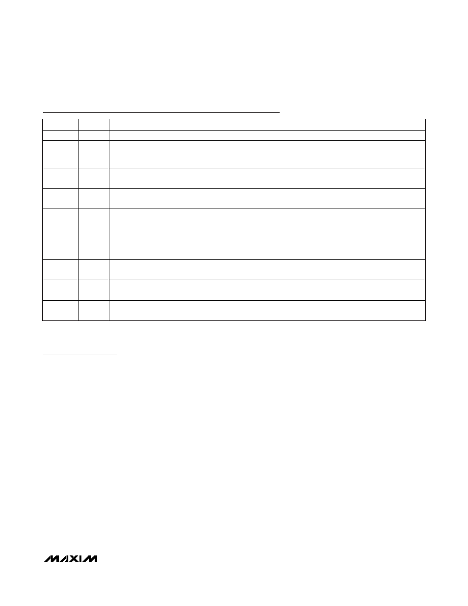
Pin Description (continued)
PIN
NAME
FUNCTION
22
V
DD
Boost Reg ul ator M OS FE T G ate D r i ve S up p l y. Byp ass V
D D
to G N D w i th a cer am i c cap aci tor of 1µF or g r eater .
23
V
CC
5V Linear Regulator Output. V
CC
provides power to the MAX17061. Bypass V
CC
to GND with a ceramic
capacitor of 1µF or greater. If V
IN
is less than or equal to 5.5V, tie V
CC
to IN to disable internal LDO and use
external 5V supply to V
CC
.
24
CCV
Step-Up Converter Compensation Pin. Connect a 0.022µF ceramic capacitor and 5.1k
Ω resistor from CCV to
GND. When the MAX17061 shuts down, CCV is discharged to 0V through an internal 20k
Ω resistor.
25
OV
Overvoltage Sense. Connect OV to the center tap of a resistive voltage-divider from V
OUT
to ground. The
detection threshold for voltage limiting at OV is 1.236V (typ).
26
ISET
Full-Scale LED Current Adjustment Pin. The resistance from ISET to GND controls the full-scale current in
each LED string:
I
LEDMAX
= 20mA x 200k
Ω/R
ISET
The acceptable resistance range is 133k
Ω < R
ISET
< 266k
Ω, which corresponds to full-scale LED current of
30mA > I
LEDMAX
> 15mA. Connect ISET to V
CC
for a default full-scale LED current of 25mA.
27
FB1
LED String 1 Cathode Connection. FB1 is the open-drain output of an internal regulator, which controls
current through FB1. FB1 can sink up to 30mA. If unused, connect FB1 to V
CC
.
28
FB2
LED String 2 Cathode Connection. FB2 is the open-drain output of an internal regulator, which controls
current through FB2. FB2 can sink up to 30mA. If unused, connect FB2 to V
CC
.
—
EP
Exposed Backside Pad. Solder to the circuit board ground plane with sufficient copper connection to ensure
low thermal resistance. See the PCB Layout Guidelines section.
Detailed Description
The MAX17061 is a high-efficiency driver for arrays of
white LEDs. It contains a fixed-frequency current-
mode PWM step-up controller, a 5V linear regulator,
dimming control circuit, SMBus interface, internal
power MOSFET, and eight regulated current sources
(see Figure 2). When enabled, the step-up controller
boosts the output voltage to provide sufficient head-
room for the current sources to regulate their respec-
tive string currents. The MAX17061 features selectable
switching frequency (500kHz, 750kHz, or 1MHz), which
allows trade-offs between external component size and
operating efficiency. The control architecture automati-
cally skips pulses at light loads to improve efficiency
and prevents overcharging the output capacitor.
WLED brightness is controlled by turning the WLEDs
on and off with a DPWM signal. The DPWM frequency
can be accurately adjusted with a resistor. The bright-
ness of the LEDs is proportional to the duty cycle of the
DPWM signal, which is controlled externally through
either a PWM or 2-wire SMBus-compatible interface, or
both. When both interfaces are used at the same time,
the product of the PWM duty cycle and SMBus com-
mand value is used for the dimming control. This
DPWM control scheme provides a full dimming range
with 8-bit resolution.
The MAX17061 has multiple features to protect the con-
troller from fault conditions. Separate feedback loops limit
the output voltage in all circumstances. The MAX17061
checks each FB_ voltage during the operation. If one or
more strings are open, the corresponding FB_ voltages
are pulled below 175mV (typ), and open-circuit fault is
detected. As a result, the respective current sources are
disabled. When one or more LEDs are shorted and the
FB_ voltage exceeds 1.1 x V
CC
, short fault is detected
and the respective current source is disabled. In either
LED open or short conditions, the fault strings are dis-
abled while other strings can still operate normally. The
controller features cycle-by-cycle current limit to provide
stable operation and soft-start protection. In a current-
limit condition, the controller shuts down after a 128µs
overcurrent fault timer expires. A thermal-shutdown cir-
cuit provides another level of protection.