Rainbow Electronics MAX17061 User Manual
Page 17
Overvoltage Protection
The SMBus interface can be used to adjust the dim-
ming, as well as shut down the MAX17061. Before the
MAX17061 receives a turn-on command from the
SMBus, it automatically remains off. In this low-power
state, most of the control circuits are turned off, and
only part of LDO is active to provide a loosely regulated
output of about 4.35V on the V
CC
pin to power the
SMBus interface. Even in PWM dimming mode, only the
PWMI interface is used for brightness control; the
MAX17061 cannot run without the SMBus interface. For
sister products without the SMBus interface, contact
MAXIM Integrated Products, Inc.
Dimming Control Register Descriptions
The MAX17061 includes four registers to monitor and
control brightness, fault status, identification, and oper-
ating mode. The slave address is 0b0101100.
The MAX17061 uses two multiplexers internally to direct
the dimming signal processing (Figure 5). These two
multiplexers are controlled by 2 bits of the device con-
trol register, PWM_SEL, and PWM_MD, respectively.
The PWM_SEL bit selects either the SMBus or the PWM
input to control the brightness. The PWM_MD bit
selects the mode in which the PWM input is to be inter-
preted. Table 2 provides a complete setting of the three
dimming modes (X means don’t care).
In PWM mode, the output LED brightness is solely con-
trolled by the percentage duty cycle of the input signal
to PWMI. In SMBus mode, the input of PWMI has no
effect on the dimming control, and only the SMBus
command to brightness control register adjusts the out-
put brightness. In DPST mode, the overall brightness
level is the normalized product of the SMBus command
setting and PWM input duty cycle. The PWM signal
starts from 100% when operating in DPST mode.
MAX17061
8-String White LED Driver with
SMBus for LCD Panel Applications
______________________________________________________________________________________
17
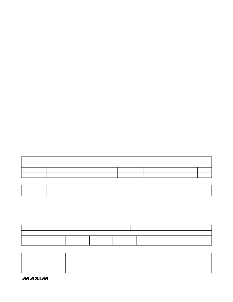
REGISTER 0x00
BRIGHTNESS CONTROL REGISTER
DEFAULT VALUE 0xFF
BRT7
BRT6
BRT5
BRT4
BRT3
BRT2
BRT1
BRT0
Bit 7 (R/W)
Bit 6 (R/W)
Bit 5 (R/W)
Bit 4 (R/W)
Bit 3 (R/W)
Bit 2 (R/W)
Bit 1 (R/W)
Bit 0
BIT FIELD
DEFINITION
DESCRIPTION
Bit [7..0]
BRT [7..0]
8-bit brightness setting, adjusting brightness levels in 256 steps, default value is 0xFF.
Brightness control register: Address is 0x00. This register is both readable and writable for all 8 bits, BRT0–BRT7,
which are used to control the LED brightness level. In SMBus dimming mode, an SMBus write byte cycle to register
0x00 sets the output brightness level. The SMBus setting of 0xFF for this register sets the backlight controller to the
maximum brightness output, and 0x00 sets the minimum backlight brightness (about 2.7%). The default value for reg-
ister 0x00 is 0xFF. A write byte cycle to register 0x00 has no effect when the backlight controller is in PWM mode. The
SMBus read byte cycle to register 0x00 returns the current brightness level, regardless of the dimming mode.
Bit field definitions:
REGISTER 0x01
DEVICE CONTROL REGISTER
DEFAULT VALUE 0x00
RESERVED
RESERVED
RESERVED
RESERVED
RESERVED
PWM_MD
PWM_SEL
BL_CTL
Bit 7
Bit 6
Bit 5
Bit 4
Bit 3
Bit 2 (R/W)
Bit 1 (R/W)
Bit 0 (R/W)
BIT FIELD
DEFINITION
DESCRIPTION
Bit 2
PWM_MD
PWM mode select (1 = absolute brightness, 0 = % change), default = 0
Bit 1
PWM_SEL
Brightness MUX select (1 = PWM pin, 0 = SMBus value), default = 0
Bit 0
BL_CTL
BL on/off (1 = on, 0 = off), default = 0
Device control register: Address is 0x01. This register is both readable and writable for Bit 0 to Bit 2. Bit 0, also
named BL_CTL, is used as ON/OFF control for the output LEDs. Bit 1 and Bit 2, named PWM_SEL and PWM_MD,
respectively, control the operating mode of the backlight controller. Bit 3 through Bit 7 are reserved bits. All reserved
bits, return zero when read, and are ignored by the controller when written. A value of 1 written to BL_CTL turns on
the backlight in 10ms or less after the write cycle completes. A value of zero written to BL_CTL immediately turns off
the backlight.
Bit field definitions: