Pin description – Rainbow Electronics MAX17061 User Manual
Page 10
MAX17061
8-String White LED Driver with
SMBus for LCD Panel Applications
10
______________________________________________________________________________________
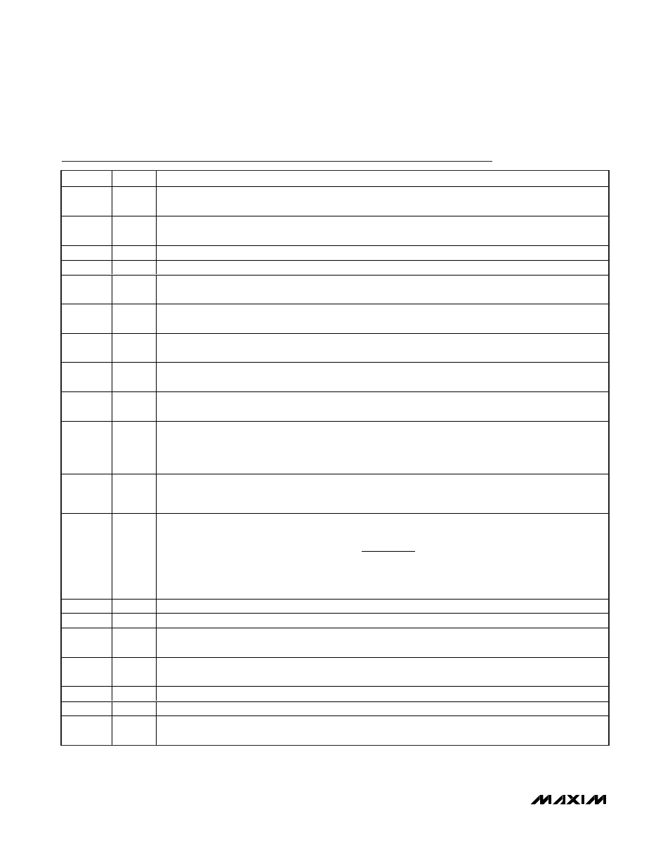
Pin Description
PIN
NAME
FUNCTION
1
FB3
LED String 3 Cathode Connection. FB3 is the open-drain output of an internal regulator, which controls
current through FB3. FB3 can sink up to 30mA. If unused, connect FB3 to V
CC
.
2
FB4
LED String 4 Cathode Connection. FB4 is the open-drain output of an internal regulator, which controls
current through FB4. FB4 can sink up to 30mA. If unused, connect FB4 to V
CC
.
3
GND
Analog Ground
4, 6, 18
N.C.
No Connection
5
FB5
LED String 5 Cathode Connection. FB5 is the open-drain output of an internal regulator, which controls
current through FB5. FB5 can sink up to 30mA. If unused, connect FB5 to V
CC
.
7
FB6
LED String 6 Cathode Connection. FB6 is the open-drain output of an internal regulator, which controls
current through FB6. FB6 can sink up to 30mA. If unused, connect FB6 to V
CC
.
8
FB7
LED String 7 Cathode Connection. FB7 is the open-drain output of an internal regulator, which controls
current through FB7. FB7 can sink up to 30mA. If unused, connect FB7 to V
CC
.
9
FB8
LED String 8 Cathode Connection. FB8 is the open-drain output of an internal regulator, which controls
current through FB8. FB8 can sink up to 30mA. If unused, connect FB8 to V
CC
.
10
OSC
O sci l l ator Fr eq uency- S el ecti on P i n. C onnect OS C to V
C C
to set the step - up conver ter ’ s osci l l ator fr eq uency to
1M H z. C onnect O S C to G N D to set the fr eq uency to 500kH z. Fl oat OS C to set the fr eq uency to 750kH z.
11
PWMI
PWM Signal Input. This PWM signal is used for brightness control in PWM mode or DPST mode. This signal
is filtered and its duty cycle is converted into a digital signal to calculate DPWM duty cycle. In PWM mode,
the DPWM duty cycle equals the input PWM duty cycle. In DPST mode, the DPWM duty cycle is the input
PWM duty cycle multiplied by the SMBus brightness command.
12
PWMO
Filtered PWM Signal Output. Connect a capacitor between PWMO and GND. The capacitor forms a lowpass
filter with an internal 40k
Ω (typ) resistor to filter the PWM signal into an analog signal whose level represents
the duty-cycle information of the input PWM signal.
13
FSET
D P W M Fr eq uency Ad j ustm ent P i n. C onnect a r esi stor fr om FS E T to GN D to set the i nter nal D P WM fr eq uency:
where:
α = 10.638
γ = 58509
This DPWM signal directly chops WLED current with the calculated duty cycle for brightness control.
14
SDA
SMBus Serial-Data Input
15
SCL
SMBus Serial-Clock Input
16
LX2
Boost Regulator Internal MOSFET Drain. Connect the inductor and the Schottky diode to LX2 node. LX2
should always be shorted to LX1 externally.
17
LX1
Boost Regulator Internal MOSFET Drain. Connect the inductor and the Schottky diode to LX1 node. LX1
should always be shorted to LX2 externally.
19
PGND2
Boost Regulator Power Ground
20
PGND1
Boost Regulator Power Ground
21
IN
Supply Input, 4.5V to 26V. V
IN
biases the internal 5V linear regulator that powers the device. Bypass IN to
GND directly at the pin with a 0.1µF or greater ceramic capacitor.
f
R
DPWM
=
×
+
10
9
α
γ
[ ]
Ω