Rainbow Electronics MAX17061 User Manual
Page 16
MAX17061
Full-Scale LED Brightness
in DPWM Dimming Control
The full-scale LED current in the DPWM dimming is
determined by resistance from the ISET pin to ground:
The acceptable resistance range is 133k
Ω < R
ISET
<
266k
Ω, which corresponds to full-scale LED current of
30mA > I
LEDMAX
> 15mA. Connect ISET to V
CC
for a
default full-scale LED current of 25mA.
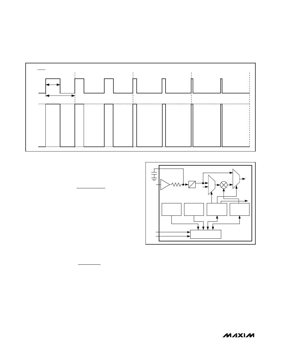
The current source output is pulse-width modulated
and synchronized with a DPWM signal to reduce jitter
and flicker noise in the display.
DPWM Frequency Setting
The MAX17061 uses an internal DPWM signal to perform
dimming control. The DPWM frequency is specified by
an external resistor connected from FSET pin to GND:
where:
α = 10.638
γ = 58509
The adjustable range for the FSET resistor, R
FSET
, is
from 42k
Ω to 464kΩ, corresponding to the DPWM fre-
quency of 200Hz to 2kHz.
Dimming Control Interfaces
The MAX17061’s dimming control circuit consists of
two interfaces: PWM and SMBus. The block diagram of
these two input interfaces is shown in Figure 5. The
dimming can be performed in three modes: PWM,
SMBus, or DPST. In PWM mode, the brightness is
adjusted by the PWM signal applied to the PWMI pin. In
SMBus mode, the brightness is adjusted by an I
2
C
command from uplink processor through the 2-wire
SMBus. In DPST mode, the brightness is adjusted by
the product of the PWM duty cycle and SMBus com-
mand value. This DPWM control provides a dimming
range with 8-bit resolution down to 2.7% and supports
Intel DPST to maximize battery life.
f
R
DPWM
=
×
+
10
9
α
γ
[ ]
Ω
I
mA
k
R
LEDMAX
ISET
=
×
20
200
Ω
8-String White LED Driver with
SMBus for LCD Panel Applications
16
______________________________________________________________________________________
PWMI
PWMO
BUFFER
A
MUX
0x03
IDENTIFICATION
REGISTER
D
1
< = 1
SCL
SMBus
INTERFACE
DPWM
SETTING
DIGITAL
MULTIPLIER
BACKLIGHT
ON/OFF
SDA
0x02
0x01
0x00
MUX
PWM_SEL
PWM_MD
SMBus AND PWM INPUT BLOCK
FAULT/STATUS
REGISTER
DEVICE
CONTROL
REGISTER
BRIGHTNESS
CONTROL
REGISTER
Figure 5. MAX17061 PWM and SMBus Interface Circuit
D = 30%
D = 12.5%
D = 6.25%
DPWM
0A
I
LEDMAX
I
LED
D = 50%
D =
t
ON
t
ON
t
DPWM
t
DPWM
DPWM DIMMING MODE
Figure 4. LED Current Control by DPWM Signal in Dimming