Electrical characteristics (continued) – Rainbow Electronics MAX17036 User Manual
Page 7
MAX17030/MAX17036
1/2/3-Phase Quick-PWM
IMVP-6.5 VID Controllers
_______________________________________________________________________________________
7
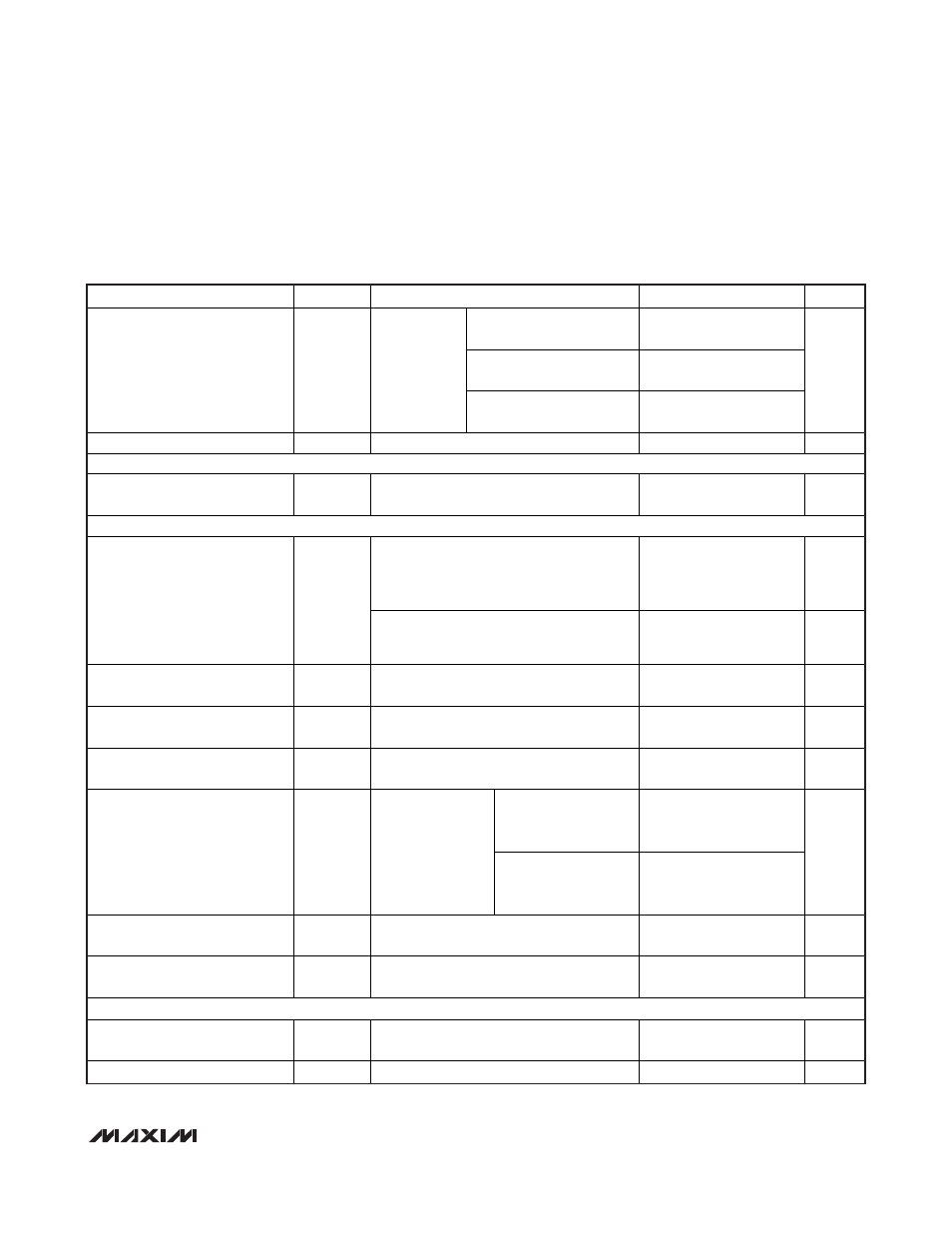
ELECTRICAL CHARACTERISTICS (continued)
(Circuit of Figure 1, V
IN
= 10V, V
CC
= V
DD
= V
SHDN
= V
PGD_IN
= V
PSI
= V
ILIM
= 5V, V
DPRSLPVR
= V
GNDS
= 0, V
CSP_
= V
CSN_
=
1.0000V, FB = FBAC, R
FBAC
= 3.57k
Ω from FBAC to CSN_, [D6–D0] = [0101000]; T
A
= -40
o
C to +105°C, unless otherwise noted.)
(Note 5)
PARAMETER
SYMBOL
CONDITIONS
MIN
TYP
MAX
UNITS
R
TON
= 96.75k
(600kHz
per phase), 167ns nominal
-15 +15
R
TON
= 200k
(300kHz
per phase), 333ns nominal
-10 +10
On-Time Accuracy
t
ON
V
IN
= 10V,
V
FB
= 1.0V,
measured at
DH1, DH2,
and PWM3
(Note 4)
R
TON
= 303.25k
(200kHz
per phase), 500ns nominal
-15 +15
%
Minimum Off-Time
t
OFF(MIN)
Measured at DH1, DH2, and PWM3 (Note 4)
400
ns
BIAS CURRENTS
Quiescent Supply Current (V
CC
) I
CC
Measured at V
CC
, DPRSLPVR = 5V, FB
forced above the regulation point
7
mA
FAULT PROTECTION
Skip mode after output reaches the
regulation voltage or PWM mode;
measured at FB with respect to the voltage
target set by the VID code (see Table 4)
250 350
mV
Output Overvoltage-Protection
Threshold
V
OVP
Soft-start, soft-shutdown, skip mode, and
output have not reached the regulation
voltage; measured at FB
1.45 1.55 V
Output Undervoltage-Protection
Threshold
V
UVP
Measured at FB with respect to the voltage
target set by the VID code (see Table 4)
-450 -350
mV
CLKEN Startup Delay and Boot
Time Period
t
BOOT
Measured from the time when FB reaches
the boot target voltage (Note 3)
20 100
µs
PWRGD Startup Delay
Measured at startup from the time when
CLKEN goes low
3 10
ms
Lower threshold,
falling edge
(undervoltage)
-350 -250
CLKEN and PWRGD Threshold
Measured at FB
with respect to the
voltage target set
by the VID code
(see Table 4),
20mV hysteresis
(typ)
Upper threshold,
rising edge
(overvoltage)
+150 +250
mV
CLKEN, PWRGD Output
Low Voltage
Low state, I
SINK
= 3mA
0.4
V
V
CC
Undervoltage-Lockout
Threshold
V
UVLO(VCC)
Rising edge, 65mV typical hysteresis,
controller disabled below this level
4.05 4.5 V
THERMAL PROTECTION
VRHOT Trip Threshold
Measured at THRM with respect to V
CC
,
falling edge, typical hysteresis = 75mV
29 31 %
VRHOT Output On-Resistance
R
ON(
VRHOT)
Low state
8