Table 3. operating mode truth table – Rainbow Electronics MAX17036 User Manual
Page 24
MAX17030/MAX17036
1/2/3-Phase Quick-PWM
IMVP-6.5 VID Controllers
24
______________________________________________________________________________________
*
Multiphase operation = All enabled phases active.
off-time expires. The on-time for each phase is based
on the input voltage to FB ratio (i.e., follows the master
on-time), but reduced by 33% in a 3-phase configura-
tion, and not reduced in a 2-phase configuration. This
maximizes the total inductor current slew rate.
After the phase-overlap mode ends, the controller auto-
matically begins with the next phase. For example, if
phase 2 provided the last on-time pulse before overlap
operation began, the controller starts switching with
phase 3 when overlap operation ends.
Nominal Output Voltage Selection
The nominal no-load output voltage (V
TARGET
) is
defined by the selected voltage reference (VID DAC)
plus the remote ground-sense adjustment (V
GNDS
) as
defined in the following equation:
where V
DAC
is the selected VID voltage. On startup, the
MAX17030/MAX17036 slew the target voltage from
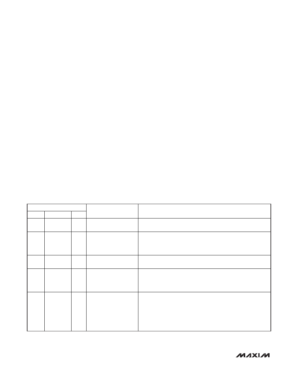
ground to the preset boot voltage. Table 3 is the operating
mode truth table.
DAC Inputs (D0–D6)
The digital-to-analog converter (DAC) programs the out-
put voltage using the D0–D6 inputs. D0–D6 are low-volt-
age (1.0V) logic inputs, designed to interface directly with
the CPU. Do not leave D0–D6 unconnected. Changing
D0–D6 initiates a transition to a new output-voltage level.
Change D0–D6 together, avoiding greater than 20ns
skew between bits. Otherwise, incorrect DAC readings
might cause a partial transition to the wrong voltage level
followed by the intended transition to the correct voltage
level, lengthening the overall transition time. The available
DAC codes and resulting output voltages are compatible
with the IMVP-6.5 (Table 4) specifications.
OFF Code
VID = 1111111 is defined as an OFF code. When the
OFF code is set, the MAX17030/MAX17036 go through
the same shutdown sequence as though SHDN has
been pulled low—output discharged to zero, CLKEN
high, and PWRGD low. Only the IC supply currents
remain at the operating levels rather than the shutdown
level. When exiting from the OFF code, the MAX17030/
MAX17036 go through the boot sequence, similar to the
sequence when SHDN is first pulled high.
V
V
V
V
TARGET
FB
DAC
GNDS
=
=
+
INPUTS
SHDN
DPRSLPVR
PSI
PHASE
OPERATION*
OPERATING MODE
GND X X
Disabled
Low-Power Shutdown Mode. DL1 and DL2 forced low, and the
controller is disabled. The supply current drops to 1µA (max).
Rising X
X
Multiphase Pulse
Skipping
1/4 R
TIME
Slew Rate
Startup/Boot. When
SHDN is pulled high, the MAX17030/
MAX17036 begin the startup sequence. Once the REF is above
1.84V, the controller enables the PWM controller and ramps the
output voltage up to the boot voltage. See Figure 9.
High Low High
Multiphase Forced-PWM
Nominal R
TIME
Slew Rate
Full Power. The no-load output voltage is determined by the selected
VID DAC code (D0–D6, Table 4).
High Low Low
(N-1)-Phase Forced-PWM
Nominal R
TIME
Slew Rate
Intermediate Power. The no-load output voltage is determined by the
selected VID DAC code (D0–D6, Table 4). When
PSI is pulled low,
the MAX17030/MAX17036 immediately disable phase 3, PWM3 is
three-state, and
DRSKP is low.
High High X
1-Phase Pulse Skipping
Nominal R
TIME
Slew Rate
Deeper Sleep Mode. The no-load output voltage is determined by the
selected VID DAC code (D0–D6, Table 4). When DPRSLPVR is pulled
high, the MAX17030/MAX17036 immediately enter 1-phase pulse-
skipping operation allowing automatic PWM/PFM switchover under
light loads. The PWRGD and
CLKEN upper thresholds are blanked.
DH2 and DL2 are pulled low, PWM3 is three-state and
DRSKP is low.
Table 3. Operating Mode Truth Table