Electrical characteristics (continued) – Rainbow Electronics MAX17036 User Manual
Page 3
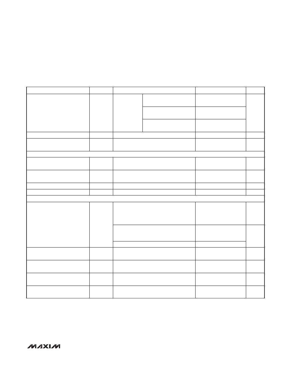
MAX17030/MAX17036
1/2/3-Phase Quick-PWM
IMVP-6.5 VID Controllers
_______________________________________________________________________________________
3
PARAMETER SYMBOL
CONDITIONS
MIN
TYP
MAX
UNITS
R
TON
= 96.75k
(600kHz
per phase), 167ns nominal
-15 +15
R
TON
= 200k
(300kHz
per phase), 333ns nominal
-10 +10
On-Time Accuracy
t
ON
V
IN
= 10V,
V
FB
= 1.0V,
measured at
DH1, DH2,
and PWM3
(Note 4)
R
TON
= 303.25k
(200kHz
per phase), 500ns nominal
-15 +15
%
Minimum Off-Time
t
OFF(MIN)
Measured at DH1, DH2, and PWM3 (Note 4)
300
375
ns
TON Shutdown Input Current
I
TON,SDN
SHDN = GND, V
IN
= 26V, V
CC
= V
DD
= 0
or 5V, T
A
= +25
°C
0.01
0.1 µA
BIAS CURRENTS
Quiescent Supply Current (V
CC
) I
CC
Measured at V
CC
, V
DPRSLPVR
= 5V, FB
forced above the regulation point
3.5 7 mA
Quiescent Supply Current (V
DD
) I
DD
Measured at V
DD
, V
DPRSLPVR
= 0, FB forced
above the regulation point, T
A
= +25
°C
0.02 1 µA
Shutdown Supply Current (V
CC
) I
CC,SDN
Measured at V
CC
,
SHDN = GND, T
A
= +25
°C 0.01 1 µA
Shutdown Supply Current (V
DD
) I
DD,SDN
Measured at V
DD
,
SHDN = GND, T
A
= +25
°C 0.01 1 µA
FAULT PROTECTION
Skip mode after output reaches the
regulation voltage or PWM mode;
measured at FB with respect to the voltage
target set by the VID code (see Table 4)
250 300 350 mV
Soft-start, soft-shutdown, skip mode, and
output have not reached the regulation
voltage; measured at FB
1.45 1.50 1.55
Output Overvoltage-Protection
Threshold
V
OVP
Minimum OVP threshold; measured at FB
0.8
V
Output Overvoltage-
Propagation Delay
t
OVP
FB forced 25mV above trip threshold
10
µs
Output Undervoltage-
Protection Threshold
V
UVP
Measured at FB with respect to the voltage
target set by the VID code (see Table 4)
-450 -400 -350 mV
Output Undervoltage-
Propagation Delay
t
UVP
FB forced 25mV below trip threshold
10
µs
CLKEN Startup Delay and
Boot Time Period
t
BOOT
Measured from the time when FB reaches
the boot target voltage (Note 3)
20 60 100 µs
ELECTRICAL CHARACTERISTICS (continued)
(Circuit of Figure 1, V
IN
= 10V, V
CC
= V
DD
= V
SHDN
= V
PGD_IN
= V
PSI
= V
ILIM
= 5V, V
DPRSLPVR
= V
GNDS
= 0, V
CSP_
= V
CSN_
=
1.0000V, FB = FBAC, R
FBAC
= 3.57k
Ω from FBAC to CSN_, [D6–D0] = [0101000]; T
A
= 0°C to +85°C, unless otherwise noted.
Typical values are at T
A
= +25°C.)