Step immunity and no r, Sense, Absolute maximum ratings – Rainbow Electronics MAX5937 User Manual
Page 2: Electrical characteristics
MAX5936/MAX5937
-48V Hot-Swap Controllers with V
IN
Step Immunity and No R
SENSE
2
_______________________________________________________________________________________
ABSOLUTE MAXIMUM RATINGS
Stresses beyond those listed under “Absolute Maximum Ratings” may cause permanent damage to the device. These are stress ratings only, and functional
operation of the device at these or any other conditions beyond those indicated in the operational sections of the specifications is not implied. Exposure to
absolute maximum rating conditions for extended periods may affect device reliability.
V
EE
, V
OUT
, PGOOD (PGOOD), LP,
STEP_MON to GND............................................+0.3V to -85V
PGOOD (PGOOD) to V
OUT
....................................-0.3V to +85V
PGOOD (PGOOD), LP, STEP_MON to V
EE
............-0.3V to +85V
GATE to V
EE
...........................................................-0.3V to +20V
UVLO to V
EE
.............................................................-0.3V to +6V
Input Current
LP (internally, duty-cycle limited).........................................1A
PGOOD (PGOOD) (continuous) .....................................80mA
GATE (during 15V clamp, continuous) ...........................30mA
GATE (during 2V clamp, continuous) .............................50mA
GATE (during gate pulldown, continuous)......................50mA
Continuous Power Dissipation (T
A
= +70°C)
8-Pin SO (derate 5.9mW/°C above +70°C)..................471mW
Operating Temperature Range ...........................-40°C to +85°C
Junction Temperature .....................................................+150°C
Storage Temperature Range ............................-65°C to +150°C
Lead Temperature (soldering, 10s) ................................+300°C
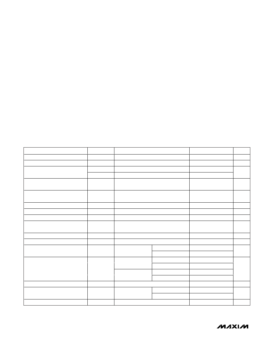
ELECTRICAL CHARACTERISTICS
(V
EE
= -10V to -80V, V
IN
= GND - V
EE
, V
STEP_MON
= V
EE
, R
LP
= 200
Ω, UVLO open, T
A
= -40°C to +85°C, unless otherwise noted.
Typical values are at V
EE
= -48V, T
A
= +25°C.) (Notes 1, 2)
PARAMETER
SYMBOL
CONDITIONS
MIN
TYP
MAX
UNITS
Operating Voltage Range
V
EE
Referenced to GND
-80
-10
V
Operating Supply Current
I
CC
0.95
1.4
mA
V
UVLO,R
lV
EE
l increasing
-33.5
-31.0
-29.5
Default V
EE
Undervoltage Lockout
V
UVLO,F
lV
EE
l decreasing
-28
V
UVLO Reference Threshold,
V
EE
Rising
V
UVLO_REF,R
V
UVLO
increasing
1.219
1.25
1.281
V
UVLO Reference Threshold,
V
EE
Falling
V
UVLO_REF,F
V
UVLO
decreasing
1.069
1.125
1.181
V
UVLO Input Resistance
20
50
k
Ω
UVLO Transient Rejection
t
OVREJ
0.8
1.5
2.25
ms
Power-Up Delay (Note 3)
t
ONDLY
80
220
380
ms
V
EE
and UVLO Glitch Rejection
(Note 4)
t
REJ
0.8
1.5
2.25
ms
V
OUT
to V
EE
Leakage Current
V
EE
= -80V, V
OUT
= GND
0.01
1
µA
LP to V
EE
Leakage Current
V
EE
= -80V, V
LP
= GND
0.01
1
µA
V
IN
= 10V
6.5
6.8
7.2
External Gate-Drive Voltage
V
GS
V
GATE
- V
EE
14 ≤ V
IN
≤ 80V
8.1
10
12.8
V
I
CLAMP
= 9mA
13.5
16
MOSFET fully
enhanced
I
CLAMP
= 20mA
17
19.5
I
CLAMP
= 1mA
2.1
2.55
GATE to V
EE
Clamp Voltage
Power-off,
V
EE
= GND
I
CLAMP
= 10mA
2.5
2.9
V
Open-Loop Gate-Charge Current
V
GATE
= V
EE
, V
OUT
= GND
-66
-52
-35
µA
V
IN
> 10V
9
14.1
GATE Pulldown Switch
On-Resistance
R
GATE
V
GATE
- V
EE
=
500mV
V
IN
> 14V
7.5
12.5
Ω
Output-Voltage Slew Rate
SR
l dV
OUT
/dt l
2.4
9
14.8
V/ms