Step immunity and no r, Sense, Appendix a – Rainbow Electronics MAX5937 User Manual
Page 17
MAX5936/MAX5937
-48V Hot-Swap Controllers with V
IN
Step Immunity and No R
SENSE
______________________________________________________________________________________
17
load-probe, and V
EE
. Because of the nature of the hot-
swap requirement, no decoupling capacitor is recom-
mended for the MAX5936/MAX5937. Because there is
no decoupling capacitor, stray inductance can result in
excessive ringing at the GND pin during power-up or
during very rapid V
IN
steps. This should be examined
in every application design since ringing at the GND
pin may exceed the absolute maximum supply rating
for the part.
Input Transient Protection
During hot plug-in/unplug and fast V
IN
steps, stray
inductance in the power path can cause voltage ring-
ing above the normal input DC value, which may
exceed the absolute maximum supply rating. An input
transient such as that caused by lightning can also put
a severe transient peak voltage on the input rail. The
following techniques are recommended to reduce the
effect of transients:
1) Minimize stray inductance in the power path using
wide traces and minimize loop area including the
power traces and the return ground path.
2) Add a high-frequency (ceramic) bypass capacitor
on the backplane as close as possible to the plug-
in connector (Figure 17).
3) Add a 1kΩ resistor in series with the MAX5936/
MAX5937’s GND pin and a 0.1µF capacitor from
GND to V
EE
to limit transient current going into this pin.
Appendix A
GATE Cycles
The power-up GATE cycle and the step GATE cycle are
quite similar but have distinct differences. Understanding
these differences may clarify application issues.
GATE Cycle During Power-Up
The power-up GATE cycle occurs during the initial
power-up of the MAX5936/MAX5937 and the associat-
ed power MOSFET and load. The power-up GATE
cycle can result in full enhancement or in a fault (all
voltages are relative to V
EE
).
Power-Up to Full Enhancement:
1) At the beginning of the power-up sequence to the
start of the power-up GATE cycle, the GATE is held
at V
EE
. Following a successful completion of the
load-probe test, GATE is held at V
EE
for an addi-
tional 350µs and then is allowed to float for 650µs.
At this point, the GATE begins to ramp with 52µA
charging the gate of the power MOSFET. [GATE
turn-on]
2) When GATE reaches the gate threshold voltage of
the power MOSFET, V
OUT
begins to ramp down
toward V
EE
. [V
OUT
ramp]
3) When V
OUT
ramps below 72% V
CB
, the GATE is
rapidly pulled to full enhancement and the power-
up GATE cycle is complete. 1.26ms after GATE is
pulled to full enhancement, PGOOD will assert. [Full
enhancement]
Figure 15. MAX5936/MAX5937 Slew Rate vs. C
SLEW
SLEW RATE vs. C
SLEW
C
SLEW
(nF)
SLEW RATE (V/ms)
100
10
1
0.1
1
10
0.01
0.1
1000
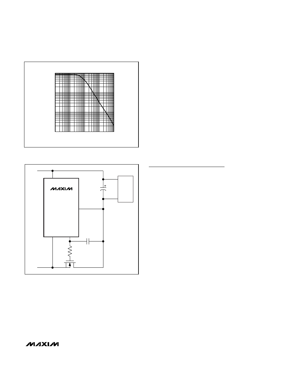
Figure 16. Adjusting the MAX5936/MAX5937 Slew Rate
MAX5936
MAX5937
V
OUT
C
LOAD
LOAD
GATE
V
EE
GND
C
SLEW
R
GATE
-48V
GND