Video inputs – Rainbow Electronics MAX4399 User Manual
Page 11
The inputs and outputs are grouped by SCART connec-
tors: TV, VCR, and AUX. While the SCART connector
supports RGB, S-video, and composite formats, RGB
and S-video share a bidirectional set of SCART connec-
tor pins. The MAX4399 supports connection of auxiliary
devices (DVD players, DVD+R/W recorders, game con-
soles, camcorders, etc.) by including full I/O support for
an auxiliary (AUX) SCART connector.
Video Inputs
All of the video amplifier inputs are AC-coupled with an
external 0.1µF capacitor. Either a clamp or bias circuit
sets the DC input level of the video signals. The clamp
circuit positions the sync tip of the CVBS, RGB, or luma
(S-VHS) signals. If the signal does not have sync, then
the clamp positions the minimum of the signal at the
clamp voltage. The bias circuit positions the chroma sig-
nal (S-VHS) at its midlevel. On the video inputs that can
receive either a chroma or a red video signal, the 2-wire
interface sets whether the clamp or bias circuit is active.
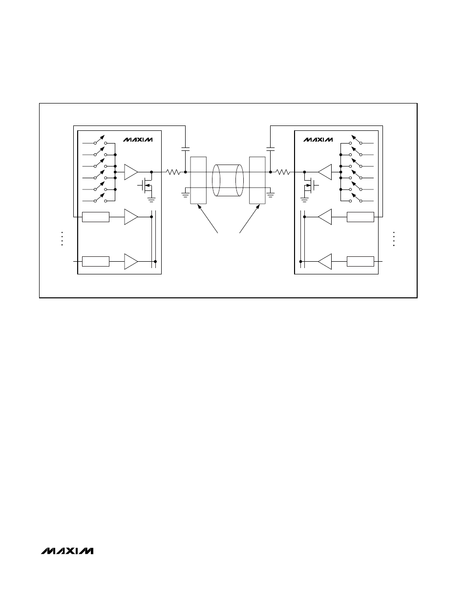
Red/chroma signals, such as TV_R/C_OUT signals are
bidirectional. When the red/chroma signal is being
used as an input, then the red/chroma output must con-
nect the 75
Ω back-termination resistor to ground, as
shown in
Figure
1, so the transmitting device can see
the proper termination on the receiving side. The
MAX4399 provides an active pulldown to G_VID on all
red/chroma outputs (AUX_R/C_OUT, TV_R/C_OUT, and
VCR_R/C_OUT).
The MPEG decoder and VCR uses the RGB format to
insert an on-screen display (OSD), usually text, onto the
TV. A fast-switching signal controls whether the RGB
signals or composite video signal appear on the TV.
The MAX4399 supports RGB as an input from either the
VCR or the MPEG decoder and as an output only to the
TV. The red video signal of the RGB format and the
chroma video signal of the S-VHS format share the
same SCART connector pin; therefore RGB signals and
S-VHS signals cannot be present at the same time.
Loop-through is possible with a composite video signal
but not with RGB signals because the RGB SCART pins
are used for both input and output.
The VCR, MPEG decoder, auxiliary device, and TV use
the S-VHS format, which is the high-quality format for the
home today. The MAX4399 supports S-VHS as an input
from the VCR, MPEG decoder, auxiliary device, and TV,
and as a separately switchable output to the TV, VCR,
and AUX SCART connectors. Because S-VHS support
was not included in the original specification of the
SCART connector, the Y signal of S-VHS and the CVBS
signal share the same SCART connector pins. If S-VHS
is present, then a composite signal must be created
MAX4399
Audio/Video Switch for Three SCART
Connectors
______________________________________________________________________________________
11
CLAMP/BIAS
CLAMP
N
CLAMP/BIAS
CLAMP
N
TV_R/C_IN
VIDEO INPUT
TV_R/C_IN
VIDEO INPUT
PIN 15
PIN 13
75
Ω
0.1
µF
0.1
µF
75
Ω
PIN 15
PIN 13
MAX4399
MAX4399
VGA
5dB, 6dB, 7dB
VGA
5dB, 6dB, 7dB
TV_R/C_OUT
TV_R/C_OUT
PULL-
DOWN
PULL-
DOWN
SCART
CABLE
SCART
CONNECTORS
Figure 1. Bidirectional SCART Pins