Electrical characteristics (continued) – Rainbow Electronics MAX17031 User Manual
Page 4
MAX17031
Dual Quick-PWM Step-Down Controller with Low-
Power LDO and RTC Regulator for MAIN Supplies
4
_______________________________________________________________________________________
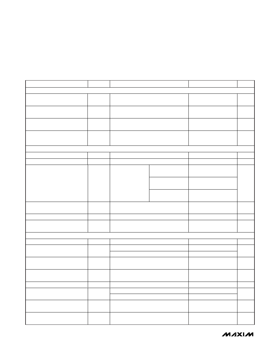
ELECTRICAL CHARACTERISTICS (continued)
(Circuit of Figure 2, no load on LDO5, RTC, OUT1, OUT2, and REF, V
IN
= 12V, V
DD
= V
CC
= V
SKIP
= 5V, ONLDO = RTC, ON1 = ON2
= V
CC
, T
A
= 0°C to +85°C, unless otherwise noted. Typical values are at T
A
= +25°C.)
PARAMETER SYMBOL
CONDITIONS
MIN
TYP
MAX
UNITS
POWER-GOOD
PGOOD Lower Trip Threshold
With respect to either error comparator
threshold, falling edge, hysteresis = 1%
-16 -13 -10 %
PGOOD Propagation Delay
t
PGOOD
OUT1 or OUT2 forced 50mV beyond
PGOOD trip threshold, falling edge
10 µs
PGOOD Output Low Voltage
ON1 or ON2 = GND (PGOOD low
impedance), I
SINK
= 4mA
0.3
V
PGOOD Leakage Current
I
PGOOD
OUT1 and OUT2 in regulation (PGOOD
high impedance), PGOOD forced to 5.5V,
T
A
= +25°C
1
µA
CURRENT LIMIT
ILIM_ Adjustment Range
0.2
2
V
ILIM_
Current
5 µA
R
ILIM
_ = 100k
(V
ILIM
_ = 500mV)
44 50 56
R
ILIM
_ = 200k
(V
ILIM
_ = 1.00V)
90 100 110
Valley Current-Limit Threshold
(Adjustable)
V
LIM
_
(VAL)
V
AGND
- V
LX
_
R
ILIM
_ = 400k
(V
ILIM
_ = 2.00V)
180 200 220
mV
Current-Limit Threshold
(Negative)
V
NEG
With respect to valley current-limit
threshold, V
SKIP
= V
REF
-120 %
Ultrasonic Current-Limit Threshold
V
NEG(US)
V
OUT2
= 3.5V, V
OUT1
= 5.3V
20
mV
Current-Limit Threshold
(Zero Crossing)
V
ZX
V
AGND
- V
LX
_,
V
SKIP
= V
CC
or GND
1.5 mV
GATE DRIVERS
DH_ Gate-Driver On-Resistance
R
DH
BST1 - LX1 and BST2 - LX2 forced to 5V
1.5
3.5
DL1, DL2; high state
1.4
4.5
DL_ Gate-Driver On-Resistance
R
DL
DL1, DL2; low state
0.5
1.5
DH_ Gate-Driver
Source/Sink Current
I
DH
DH1, DH2 forced to 2.5V,
BST1 - LX1 and BST2 - LX2 forced to 5V
2 A
DL_ Gate-Driver Source Current
I
DL
(SOURCE)
DL1, DL2 forced to 2.5V
1.7
A
DL_ Gate-Driver Sink Current
I
DL (SINK)
DL1, DL2 forced to 2.5V
3.3
A
DL1, DL2 rising (Note 4)
30
Dead Time
t
DEAD
DH1, DH2 rising (Note 4)
35
ns
Internal BST_ Switch
On-Resistance
R
BST
I
BST
_ = 10mA, V
DD
= 5V
5.5
BST_Leakage Current
V
BST
_ = 26V, T
A
= +25°C;
OUT1 and OUT2 above regulation threshold
0.1 5 µA