Electrical characteristics (continued) – Rainbow Electronics MAX17031 User Manual
Page 3
MAX17031
Dual Quick-PWM Step-Down Controller with Low-
Power LDO and RTC Regulator for MAIN Supplies
_______________________________________________________________________________________
3
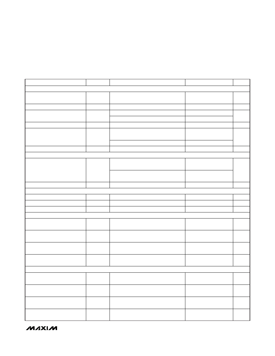
PARAMETER
SYMBOL
CONDITIONS
MIN
TYP
MAX
UNITS
LINEAR REGULATOR (LDO5)
LDO5 Output-Voltage Accuracy
V
LDO5
V
IN
= 6V to 24V, ON1 = GND,
0 < I
LDO5
< 100mA
4.90 5.0 5.10 V
LDO5 Short-Circuit Current
LDO5 = GND
100
260
mA
Falling edge of OUT1
-11.0
-8.8
-6.0
LDO5 Regulation Reduction/
Bootstrap Switchover Threshold
Rising edge of OUT1
-7.0
%
LDO5 Bootstrap Switch Resistance
LDO5 to OUT1, V
OUT1
= 5V (Note 3)
1.9
4.5
Falling edge of V
CC
, PWM disabled
below this threshold
3.8 4.0 4.3
V
CC
Undervoltage Lockout
Threshold
Rising edge of V
CC
4.2
V
Thermal-Shutdown Threshold
T
SHDN
Hysteresis = 10
°C
160
°C
3.3V ALWAYS-ON LINEAR REGULATOR (RTC)
ON1 = ON2 = GND, V
IN
= 6V to 24V,
0 < I
RTC
< 5mA
3.23 3.33 3.43
RTC Output-Voltage Accuracy
V
RTC
ON1 = ON2 = ONLDO = GND,
V
IN
= 6V to 24V, 0 < I
RTC
< 5mA
3.19 3.47
V
RTC Short-Circuit Current
RTC = GND
5
22
mA
REFERENCE (REF)
Reference Voltage
V
REF
V
CC
= 4.5V to 5.5V, I
REF
= 0
1.980
2.00
2.020
V
Reference Load Regulation Error
V
REF
I
REF
= -20µA to +50µA
-10
+10
mV
REF Lockout Voltage
V
REF(UVLO)
Rising edge, 350mV (typ) hysteresis
1.95
V
OUT1 FAULT DETECTION
OUT1 Overvoltage and PGOOD
Trip Threshold
With respect to error comparator threshold
10
13
16
%
OUT1 Overvoltage Fault
Propagation Delay
t
OVP
OUT1 forced 50mV above trip threshold
10
µs
OUT1 Undervoltage Protection
Trip Threshold
With respect to error comparator threshold
65
70
75
%
OUT1 Output Undervoltage
Fault Propagation Delay
t
UVP
10 µs
OUT2 FAULT DETECTION
OUT2 Overvoltage and PGOOD
Trip Threshold
With respect to error comparator threshold
10
13
16
%
OUT2 Overvoltage Fault
Propagation Delay
t
OVP
OUT2 forced 50mV above trip threshold
10
µs
OUT2 Undervoltage Protection
Trip Threshold
With respect to error comparator threshold
65
70
75
%
OUT2 Output Undervoltage Fault
Propagation Delay
t
UVP
10 µs
ELECTRICAL CHARACTERISTICS (continued)
(Circuit of Figure 2, no load on LDO5, RTC, OUT1, OUT2, and REF, V
IN
= 12V, V
DD
= V
CC
= V
SKIP
= 5V, ONLDO = RTC, ON1 = ON2
= V
CC
, T
A
= 0°C to +85°C, unless otherwise noted. Typical values are at T
A
= +25°C.)