Pin description (continued) – Rainbow Electronics MAX17031 User Manual
Page 11
MAX17031
Dual Quick-PWM Step-Down Controller with Low-
Power LDO and RTC Regulator for MAIN Supplies
______________________________________________________________________________________
11
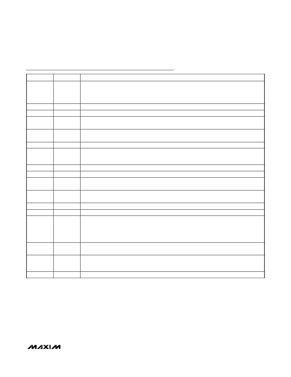
Pin Description (continued)
PIN
NAME
FUNCTION
9 PGOOD
Open-Drain Power-Good Output for SMPS1 and SMPS2. PGOOD is low when either output voltage is
more than 15% (typ) below the nominal regulation threshold, during soft-start, in shutdown, when
either SMPS is disabled, and after the fault latch has been tripped. After the soft-start circuit has
terminated, PGOOD becomes high impedance if both outputs are in regulation.
10
ON1
Enable Input for SMPS1. Drive ON1 high to enable SMPS1. Drive ON1 low to shut down SMPS1.
11
DH1
High-Side Gate-Driver Output for SMPS1. DH1 swings from LX1 to BST1.
12 LX1
Inductor Connection for SMPS1. Connect LX1 to the switched side of the inductor. LX1 is the lower
supply rail for the DH1 high-side gate driver.
13 BST1
Boost Flying Capacitor Connection for SMPS1. Connect to an external capacitor as shown in
Figure 1. An optional resistor in series with BST1 allows the DH1 turn-on current to be adjusted.
14
DL1
Low-Side Gate-Driver Output for SMPS1. DL1 swings from power GND to V
DD.
15 V
DD
Supply Voltage Input for the DL_ Gate Drivers. V
DD
is internally connected to the drain of the HVPV
BST diode switch. Connect to a 5V supply, and bypass V
DD
to power GND with a 1µF or greater
ceramic capacitor.
16 GND
Analog
and
Power
Ground
17
DL2
Low-Side Gate-Driver Output for SMPS2. DL2 swings from power GND to V
DD.
18 BST2
Boost Flying Capacitor Connection for SMPS2. Connect to an external capacitor as shown in
Figure 1. An optional resistor in series with BST2 allows the DH2 turn-on current to be adjusted.
19 LX2
Inductor Connection for SMPS2. Connect LX2 to the switched side of the inductor. LX2 is the lower
supply rail for the DH2 high-side gate driver.
20
DH2
High-Side Gate-Driver Output for SMPS2. DH2 swings from LX2 to BST2.
21
ON2
Enable Input for SMPS2. Drive ON2 high to enable SMPS2. Drive ON2 low to shut down SMPS2.
22 SKIP
Pulse-Skipping Control Input. This three-level input determines the operating mode for the
switching regulators:
High (> 2V) = pulse-skipping mode
Middle (1.8V) = forced-PWM mode
GND = ultrasonic mode
23 OUT2
Output-Voltage Sense Input for SMPS2. OUT2 is an input to the Quick-PWM on-time one-shot timer.
OUT2 also serves as the feedback input for the preset 3.3V.
24 ILIM2
Valley Current-Limit Adjustment for SMPS2. The GND - LX2 current-limit threshold is 1/10 the
voltage present on ILIM2 over a 0.2V to 2V range. An internal 5µA current source allows this
voltage to be set with a single resistor between ILIM2 and analog ground.
—
EP
Exposed Pad. Connect backside exposed pad to analog GND and power GND.