Rainbow Electronics MAX17031 User Manual
Page 17
Modes of Operation
Forced-PWM Mode (V
SKIP
= 1.8V)
The low-noise forced-PWM mode (V
SKIP
= 1.8V) dis-
ables the zero-crossing comparator, which controls the
low-side switch on-time. This forces the low-side gate-
drive waveform to constantly be the complement of the
high-side gate-drive waveform, so the inductor current
reverses at light loads while DH maintains a duty factor
of V
OUT
/V
IN
. The benefit of forced-PWM mode is to
keep the switching frequency fairly constant. However,
forced-PWM operation comes at a cost: the no-load 5V
bias current remains between 20mA to 60mA depend-
ing on the switching frequency and MOSFET selection.
The MAX17031 automatically uses forced-PWM operation
during shutdown regardless of the SKIP configuration.
Automatic Pulse-Skipping Mode (V
SKIP
> 2V)
In skip mode (V
SKIP
> 2V), an inherent automatic
switchover to PFM takes place at light loads. This
switchover is affected by a comparator that truncates
the low-side switch on-time at the inductor current’s
zero crossing. The zero-crossing comparator output is
set by the differential voltage across LX and GND.
DC output-accuracy specifications refer to the integrated
threshold of the error comparator. When the inductor is
in continuous conduction, the MAX17031 regulates the
valley of the output ripple and the internal integrator
removes the actual DC output-voltage error caused by
the output-ripple voltage and internal slope compensa-
tion. In discontinuous conduction (V
SKIP
> 2V and I
OUT
< I
LOAD(SKIP)
), the integrator cannot correct for the low-
frequency output ripple error, so the output voltage has
a DC regulation level higher than the error comparator
threshold by approximately 1.5% due to slope compen-
sation and output ripple voltage.
Ultrasonic Mode (V
SKIP
= GND)
Shorting SKIP to ground activates a unique pulse-
skipping mode with a guaranteed minimum switching
frequency of 20kHz. This ultrasonic pulse-skipping
mode eliminates audio-frequency modulation that would
otherwise be present when a lightly loaded controller
automatically skips pulses. In ultrasonic mode, the con-
troller automatically transitions to fixed-frequency PWM
operation when the load reaches the same critical con-
duction point (I
LOAD(SKIP)
) that occurs when normally
pulse skipping.
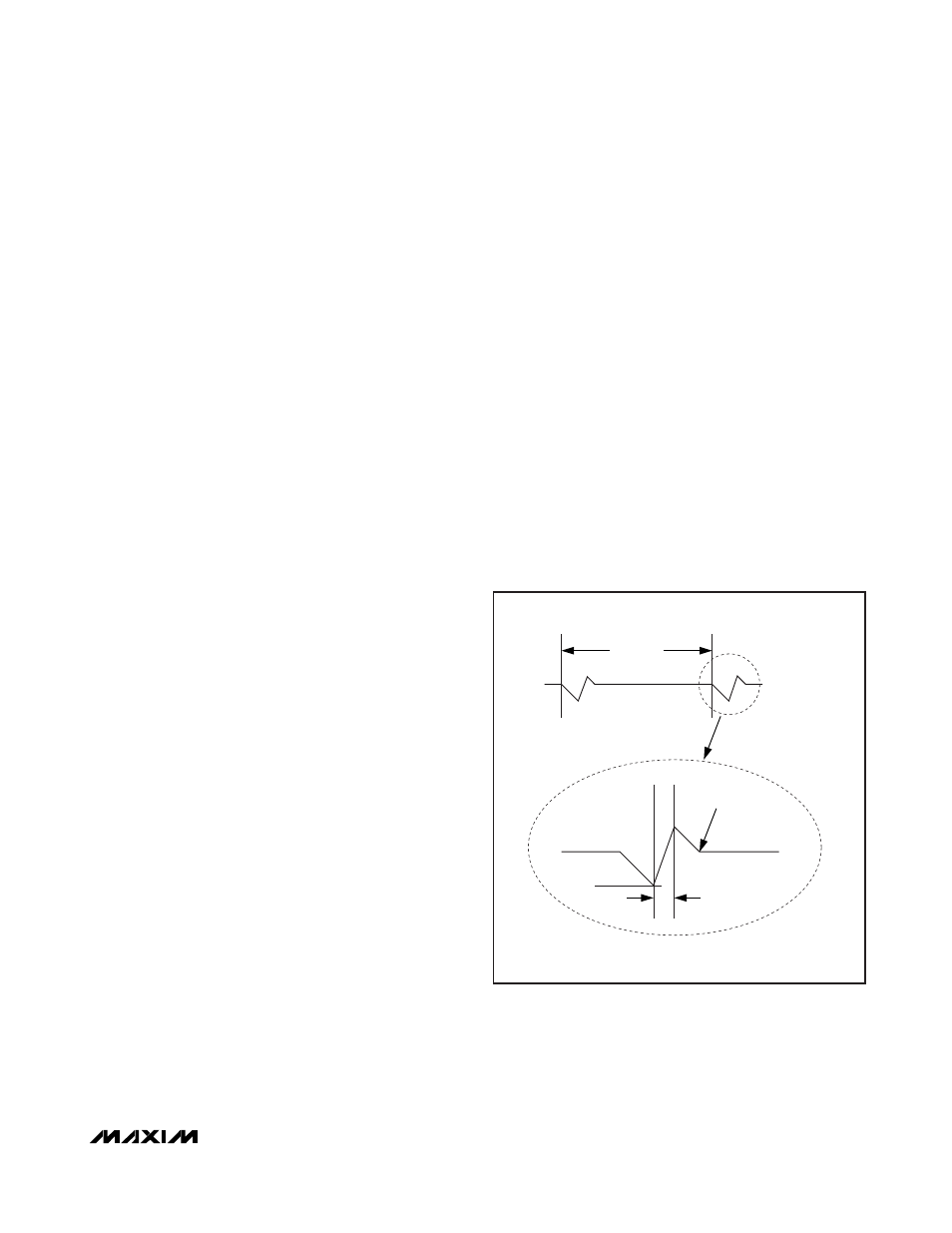
An ultrasonic pulse occurs (Figure 4) when the con-
troller detects that no switching has occurred within the
last 37µs. Once triggered, the ultrasonic circuitry pulls
DL high, turning on the low-side MOSFET to induce a
negative inductor current. After the inductor current
reaches the negative ultrasonic current threshold, the
controller turns off the low-side MOSFET (DL pulled
low) and triggers a constant on-time (DH driven high).
When the on-time has expired, the controller reenables
the low-side MOSFET until the inductor current drops
below the zero-crossing threshold. Starting with a DL
pulse greatly reduces the peak output voltage when
compared to starting with a DH pulse.
The output voltage at the beginning of the ultrasonic
pulse determines the negative ultrasonic current thresh-
old, corresponding to:
where R
CS
is the current-sense resistance seen across
LX to GND.
V
I R
NEG US
L CS
(
)
=
MAX17031
Dual Quick-PWM Step-Down Controller with Low-
Power LDO and RTC Regulator for MAIN Supplies
______________________________________________________________________________________
17
ON-TIME (t
ON
)
I
SONIC
0
INDUCTOR
CURRENT
ZERO-CROSSING
DETECTION
40
µs (MAX)
Figure 4. Ultrasonic Waveforms