Design procedure – Rainbow Electronics MAX17031 User Manual
Page 19
Power-Good Outputs (PGOOD)
and Fault Protection
PGOOD is the open-drain output that continuously
monitors both output voltages for undervoltage and
overvoltage conditions. PGOOD is actively held low in
shutdown (ON1 or ON2 = GND), during soft-start, and
soft-shutdown. Approximately 20µs (typ) after the soft-
start terminates, PGOOD becomes high impedance as
long as both output voltages exceed 85% of the nomi-
nal fixed-regulation voltage. PGOOD goes low if the
output voltage drops 15% below the regulation voltage,
or if the SMPS controller is shut down. For a logic-level
PGOOD output voltage, connect an external pullup
resistor between PGOOD and the logic power supply.
A 100k
Ω pullup resistor works well in most applications.
Overvoltage Protection (OVP)
When the output voltage rises 15% above the fixed-
regulation voltage, the controller immediately pulls
PGOOD low, sets the overvoltage fault latch, and imme-
diately pulls the respective DL_ high—clamping the
output fault to GND. Toggle either ON1 or ON2 input, or
cycle V
CC
power below its POR threshold to clear the
fault latch and restart the controller.
Undervoltage Protection (UVP)
When the output voltage drops 30% below the fixed-
regulation voltage, the controller immediately pulls the
PGOOD low, sets the undervoltage fault latch, and
begins the shutdown sequence. After the output volt-
age drops below 0.1V, the synchronous rectifier turns
on, clamping the output to GND regardless of the out-
put voltage. Toggle either ON1 or ON2 input, or cycle
V
CC
power below its POR threshold to clear the fault
latch and restart the controller.
Thermal-Fault Protection (T
SHDN
)
The MAX17031 features a thermal-fault protection cir-
cuit. When the junction temperature rises above
+160°C, a thermal sensor activates the fault latch, pulls
PGOOD low, enables the 10
Ω discharge circuit, and
disables the controller—DH and DL pulled low. Toggle
ONLDO or cycle IN power to reactivate the controller
after the junction temperature cools by 15°C.
Design Procedure
Firmly establish the input-voltage range and maximum
load current before choosing an inductor operating
point (ripple-current ratio). The primary design goal is
choosing a good inductor operating point, and the fol-
lowing three factors dictate the rest of the design:
•
Input Voltage Range: The maximum value (V
IN(MAX)
)
must accommodate the worst-case, high AC-
adapter voltage. The minimum value (V
IN(MIN)
)
must account for the lowest battery voltage after
drops due to connectors, fuses, and battery-selec-
tor switches. If there is a choice at all, lower input
voltages result in better efficiency.
•
Maximum Load Current: There are two values to
consider. The peak load current (I
LOAD(MAX)
) deter-
mines the instantaneous component stresses and fil-
tering requirements and thus drives output capacitor
selection, inductor saturation rating, and the design of
the current-limit circuit. The continuous load current
(I
LOAD
) determines the thermal stresses and thus dri-
ves the selection of input capacitors, MOSFETs, and
other critical heat-contributing components.
MAX17031
Dual Quick-PWM Step-Down Controller with Low-
Power LDO and RTC Regulator for MAIN Supplies
______________________________________________________________________________________
19
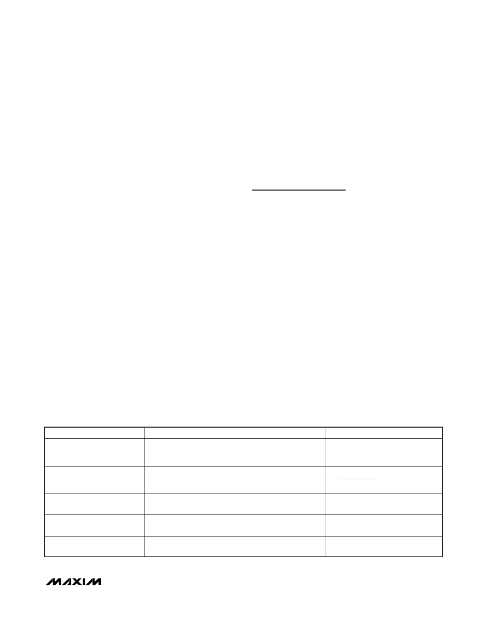
MODE
CONTROLLER STATE
DRIVER STATE
Shutdown (ON_ = High to Low)
Output UVP (Latched)
Voltage soft-shutdown initiated. Internal error-amplifier
target slowly ramped down to GND and output actively
discharged (automatically enters forced-PWM mode).
DL driven high and DH pulled low
after soft-shutdown completed
(output < 0.1V).
Output OVP (Latched)
Controller shuts down and EA target internally slewed
down. Controller remains off until ON_ toggled or V
CC
power cycled.
DL immediately driven high,
DH pulled low.
UVLO (V
CC
Falling-Edge)
Thermal Fault (Latched)
SMPS controller disabled (assuming ON_ pulled high),
10
output discharge active.
DL and DH pulled low.
UVLO (V
CC
Rising Edge)
SMPS controller disabled (assuming ON_ pulled high),
10
output discharge active.
DL driven high,
DH pulled low.
V
CC
Below POR
SMPS inactive, 10
output discharge active.
DL driven high,
DH pulled low.
Table 3. Fault Protection and Shutdown Operation Table