Converter electrical characteristics – Rainbow Electronics ADC12L038 User Manual
Page 4
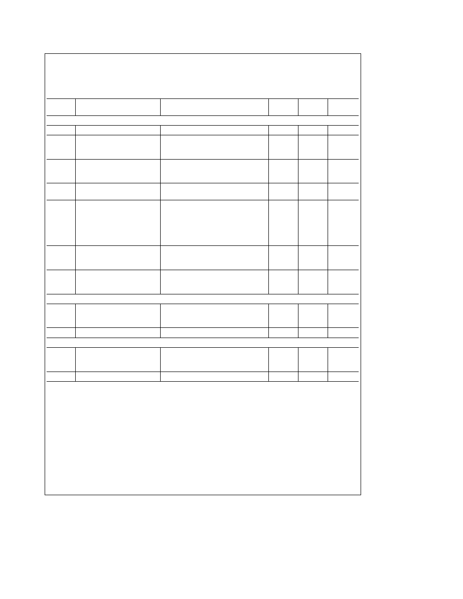
Converter Electrical Characteristics
(Continued)
The following specifications apply for V
a
e
V
A
a
e
V
D
a
e a
3 3 V
DC
V
REF
a
e a
2 500 V
DC
V
REF
b
e
0 V
DC
12-bit a
sign conversion mode f
CK
e
f
SK
e
5 MHz R
S
e
25X source impedance for V
REF
a
and V
REF
b
s
25X fully-differential input
with fixed 1 250V common-mode voltage and 10(t
CK
) acquisition time unless otherwise specified Boldface limits apply for
T
A
e
T
J
e
T
MIN
to T
MAX
all other limits T
A
e
T
J
e
25 C (Notes 7 8 and 9)
Symbol
Parameter
Conditions
(Note 10)
Typical
Limits
(Limits)
Units
(Note 11)
STATIC CONVERTER CHARACTERISTICS
(Continued)
Negative Full-Scale Error
8-bit a sign mode (Note 12)
g
1 2
LSB (max)
Offset Error
8-bit a sign mode
after Auto-Zero (Note 13)
g
1 2
LSB (max)
V
IN
(a) e V
IN
(b) e a 1 250V
TUE
Total Unadjusted Error
8-bit a sign mode
after Auto-Zero
g
3 4
LSB (max)
(Notes 12 13 and 14)
Multiplexer Channel to Channel
g
0 05
LSB
Matching
Power Supply Sensitivity
V
a
e a
3 3V
g
10%
Offset Error
g
0 5
g
1
LSB (max)
a
Full-Scale Error
g
0 5
g
1 5
LSB (max)
b
Full-Scale Error
g
0 5
g
1 5
LSB (max)
a
Integral Linearity Error
g
0 5
LSB
b
Integral Linearity Error
g
0 5
LSB
Output Data from
(Note 20)
a
10
LSB (max)
‘‘12-Bit Conversion of Offset’’
b
10
LSB (min)
(see Table V)
Output Data from
(Note 20)
4095
LSB (max)
‘‘12-Bit Conversion of Full-Scale’’
4093
LSB (min)
(see Table V)
UNIPOLAR DYNAMIC CONVERTER CHARACTERISTICS
S (NaD)
Signal-to-Noise Plus
f
IN
e
1 kHz V
IN
e
2 5 V
PP
69 4
dB
Distortion Ratio
f
IN
e
20 kHz V
IN
e
2 5 V
PP
68 3
dB
f
IN
e
40 kHz V
IN
e
2 5 V
PP
65 7
dB
b
3 dB Full Power Bandwidth
V
IN
e
2 5 V
PP
where S (NaD) drops 3 dB
31
kHz
DIFFERENTIAL DYNAMIC CONVERTER CHARACTERISTICS
S (NaD)
Signal-to-Noise Plus
f
IN
e
1 kHz V
IN
e
g
2 5V
77 0
dB
Distortion Ratio
f
IN
e
20 kHz V
IN
e
g
2 5V
73 9
dB
f
IN
e
40 kHz V
IN
e
g
2 5V
67 0
dB
b
3 dB Full Power Bandwidth
V
IN
e
g
2 5V where S (NaD) drops 3 dB
40
kHz
4