Maxq7667, Echo receive path, Low-noise amplifier (lna) – Rainbow Electronics MAXQ7667 User Manual
Page 17: Diagnostic signals, Internally generated signal (figure 2). the 2mv
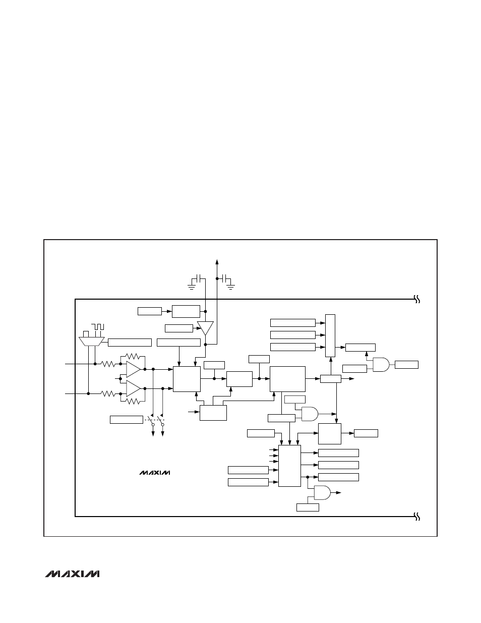
MAXQ7667
Echo Receive Path
Low-Noise Amplifier (LNA)
The LNA provides a 40V/V fixed gain to the input signal.
The differential inputs of the LNA are ECHOP and
ECHON. For proper biasing of the LNA, AC-couple the
transducer or any external circuitry to ECHOP and
ECHON. For a single-ended input signal, AC-couple the
signal to ECHOP with a 0.01µF capacitor and connect
ECHON to AGND through a 0.01µF capacitor placed as
close as possible to the signal source. The outputs of the
LNA connect to the inputs of a 16-bit sigma-delta ADC
and can connect internally to the AIN0 and AIN1 inputs
of the SAR ADC for external monitoring (Figure 2).
Diagnostic Signals
An analog multiplexer located at the input of the LNA
selects one of three possible signals for processing by
the echo receive path; the normal echo signal AC-cou-
pled to the ECHOP and ECHON inputs, 0V signal, or a
2mV
P-P
internally generated signal (Figure 2). The
2mV
P-P
square-wave signal, with frequency and duty
cycle matching the burst signal, allows the echo
receive chain to process a simulated echo.
MAXQ7667
0.47
µF
AGND
REFGB
0.47
µF
TO EXTERNAL VOLTAGE
REFERENCE
AGND
REF
VARIABLE
GAIN SIGMA-
DELTA ADC
FIFO
8 x 16
FIFO
CONTROL
BANDPASS
FILTER
CLOCK
CONTROL
ECHO
RECEIVE
CLOCK
RCVC[4:0]:RCVGN[4:0]
RCVC[7:6]:LNAISEL[1:0]
RCVC.8:LNAOSEL
BPFI[15:0]
APE.13:RSARE
2.5V
BANDGAP REF
APE.12:BGE
FULL-WAVE
RECTIFIER PLUS
LOWPASS FILTER
R*
R*
*R = ECHO INPUT RESISTANCE. SEE THE ELECTRICAL CHARACTERISTICS SECTION.
40R*
AIN0
TO SAR ADC
AIN1
0V
2mV
P-P
40R*
LNA
AVDD/2
ECHOP
ECHON
MUX
BPFO[15:0]
LPFD[15:0]
CMPC[14:0]:CMPH[14:0]
CMPT[15:0]
LPFC[15:12]:FFIL[3:0]
LPFC[2.0]:FFLS[2:0]
LPFC.7:FFOV
ASR.2:LPFFL
LPFC[11:8]:FFDP[3:0]
CMPC.15:CMPP
ASR.12:CMPLVL
AIE.3:CMPIE
LPFF[15:0]
ASR.3:CMPI
COMPARATOR
AIE.1:LPFIE
ASR.1:LPFRDY
LPFC.3:FFLD
TIMER 0
TIMER 1
TIMER 2
DATA READY
INTERRUPT
AIE.2:LFLIE
Figure 2. Echo Receive Path
16-Bit, RISC, Microcontroller-Based,
Ultrasonic Distance-Measuring System
______________________________________________________________________________________
17