Detailed description, Burst controller – Rainbow Electronics MAXQ7667 User Manual
Page 16
MAXQ7667
16-Bit, RISC, Microcontroller-Based,
Ultrasonic Distance-Measuring System
16
______________________________________________________________________________________
Detailed Description
The ultrasonic distance-measurement peripherals in the
MAXQ7667 include a burst signal generator for
acoustic transmission and mixed signal circuits for
amplifying and digitizing echo signals ranging between
25kHz and 100kHz. The burst signal is a square wave
with adjustable duty cycle and pulse count. The burst is
derived either directly from the system clock or from a
programmable PLL locked to the system clock. The
MAXQ7667 effectively digitizes the echo signals
received at the ECHOP and ECHON inputs using an
LNA, sigma-delta ADC with variable analog gain ampli-
fier, noise-limiting digital bandpass filter, digital full-
wave rectifier, and a digital lowpass filter (see the
Typical Application Circuit/Functional Diagram
). The
device detects echo signals at the burst frequency with
amplitudes ranging from 10µV
P-P
to 100mV
P-P
. Echoes
greater than 100mV
P-P
and less than 2V
P-P
are internal-
ly clipped but do not saturate the receiver. To optimize
echo reception, the clock used for processing the echo
locks to the burst frequency. The MAXQ7667’s burst
generator can generate higher frequencies, but the
maximum usable frequency for the echo receive path is
100kHz . For applications requiring transducer frequen-
cies above 100kHz, implement an external echo
receive path. The SAR ADC can then digitize the fil-
tered echo envelope.
An integrated 16-bit RISC µC (MAXQ20) provides tim-
ing control, signal processing, and data I/O. The 16-bit
Harvard architecture RISC core executes most instruc-
tions in a single clock cycle from instruction fetch to
cycle completion. The MAXQ20 provides optimal per-
formance for noise-sensitive analog applications.
The MAXQ7667 includes a 13.5MHz RC oscillator,
external crystal oscillator, watchdog timer, schedule
timer, three general-purpose Type 2 timers/counters,
two 8-bit GPIO ports, SPI interface, JTAG interface, LIN
capable UART interface, 12-bit SAR ADC with five mul-
tiplexed input channels, supply-voltage monitors, and a
voltage reference for communication, diagnostics, and
miscellaneous support.
Burst Controller
The MAXQ7667 provides a square-wave burst signal at
the BURST output. Use the burst control to transmit an
ultrasonic signal. Typical applications use the burst sig-
nal to switch an external transistor that drives a high-
voltage transformer, which excites the transducer (see
the
Typical Application Circuit/Functional Diagram
).
Use software to configure the duty cycle, frequency,
number of pulses, and drive current of the burst. See
Section 17 of the
MAXQ7667 User’s Guide
.
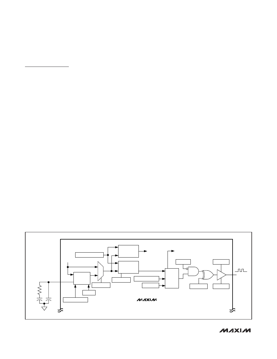
Derive the burst signal either directly from the system
clock or from a programmable oscillator phase locked
to the system clock (Figure 1). Using the system clock
limits the burst frequency to one of 16 choices. Integer
division of the system clock generates these 16 fre-
quencies. The PLL allows a fractional division of the
system clock. Any frequency within the PLL range is
selectable to a resolution of 0.13% or better.
When using the internal PLL, connect external filter
components (C1, R1, and C2) to FILT as shown in
Figure 1. These components filter the analog voltage
that controls the VCO in the PLL. The filter component
values shown in the figure are suitable for the entire
PLL frequency range.
MAXQ7667
C2
330pF
SYSTEM
CLOCK
(f
SYSCLK
)
ECHO
RECEIVE
CLOCK
PLL
C1
33nF
FILT
R1
24k
Ω
PWM
2mV
P-P
DIAGNOSTIC
BURST
1
0
BTRN.10:BCKS
BPH[9:0]
PLLF[10:9]:PLLC[1:0]
BTRN[15:12]:BDIV[3:0]
BTRN[7:0]:BCNT[7:0]
BPH.15:BSTT
BTRN.9:BTRI
BPH.14:BDS
BTRN.11:BPOL
BTRN.8:BGT
BURST
PLLF[8:0]
BURST CLOCK
GENERATOR
RECEIVE CLOCK
PRESCALE
Figure 1. Burst Transmission Stage