In-circuit debug, Figure 9. in-circuit debugger – Rainbow Electronics MAXQ2010 User Manual
Page 29
MAXQ2010
16-Bit Mixed-Signal Microcontroller with LCD
______________________________________________________________________________________
29
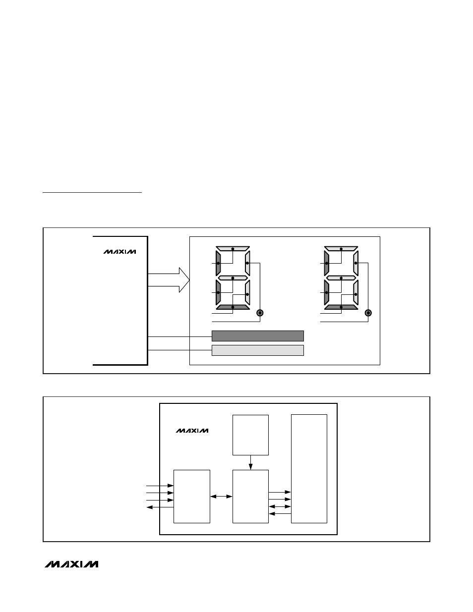
A simple LCD-segmented glass interface example
demonstrates the minimal hardware required to inter-
face to a MAXQ2010 microcontroller. A two-character
LCD is controlled, with each character containing
seven segments plus decimal point. The LCD controller
is configured for 1/2 duty-cycle operation, meaning the
active segment is controlled using a combination of
segment signals and COM0 or COM1 signals are used
to select the active display. See Figure 8.
In-Circuit Debug
Embedded debugging capability is available through
the JTAG-compatible TAP. Embedded debug hardware
and embedded ROM firmware provide in-circuit debug-
ging capability to the user application, eliminating the
need for an expensive in-circuit emulator. Figure 9
shows a block diagram of the in-circuit debugger. The
in-circuit debug features include the following:
• A hardware debug engine.
• A set of registers able to set breakpoints on register,
code, or data accesses.
• A set of debug service routines stored in the utility
ROM.
The embedded hardware debug engine is an indepen-
dent hardware block in the microcontroller. The debug
TAP
CONTROLLER
CPU
DEBUG
ENGINE
DEBUG
SERVICE
ROUTINES
(UTILITY ROM)
CONTROL
BREAKPOINT
ADDRESS
DATA
TMS
TCK
TDI
TDO
MAXQ2010
Figure 9. In-Circuit Debugger
SEG0
SEG1
SEG2
SEG3
COM0
SEG[0:7]
CONNECTED TO DARK GREY SEGMENTS
COM1
CONNECTED TO LIGHT GREY SEGMENTS
SEG4
SEG5
SEG6
SEG7
MAXQ2010
Figure 8. Two-Character, 1/2 Duty, LCD Interface Example