Pin description – Rainbow Electronics MAXQ2010 User Manual
Page 16
MAXQ2010
16-Bit Mixed-Signal Microcontroller with LCD
16
______________________________________________________________________________________
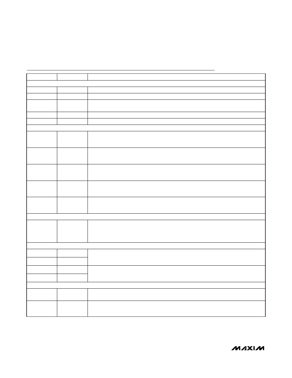
Pin Description
PIN
NAME
FUNCTION
POWER PINS
40, 63, 96
DVDD
Digital Supply Voltage
41, 66, 95
DGND
Digital Ground
98, 99
REGOUT
Regulator Capacitor. These pins must be shorted together at the pins and then connected to
ground through a 1.0μF ceramic capacitor.
82
AVDD
Analog Supply Voltage
79
AGND
Analog Ground
ANALOG MEASUREMENT PINS
70 AVREF
Analog Voltage Reference. When using an external reference source, this pin must be
connected to 1μF and 0.01μF filter capacitors in parallel. When using an internal reference
source, this pin must be connected to a 0.01μF capacitor.
78, 77
AN0, AN1
Analog Input 0:1. This pair of analog inputs can function as two single-ended inputs or one
differential pair. When functioning in differential mode, AN0 is the positive input and AN1 is
the negative input.
76, 75
AN2, AN3
Analog Input 2:3. This pair of analog inputs can function as two single-ended inputs or one
differential pair. When functioning in differential mode, AN2 is the positive input and AN3 is
the negative input.
74, 73
AN4, AN5
Analog Input 4:5. This pair of analog inputs can function as two single-ended inputs or one
differential pair. When functioning in differential mode, AN4 is the positive input and AN5 is
the negative input.
72, 71
AN6, AN7
Analog Input 6:7. This pair of analog inputs can function as two single-ended inputs or one
differential pair. When functioning in differential mode, AN6 is the positive input and AN7 is
the negative input.
RESET PIN
92
RST
Digital, Active-Low, Reset Input/Output. The CPU is held in reset when this pin is low and
begins executing from the reset vector when released. The pin includes pullup current source
and should be driven by an open-drain, external source capable of sinking in excess of 4mA.
This pin is driven low as an output when an internal reset condition occurs.
CLOCK PINS
81 32KIN
80 32KOUT
32kHz Crystal Input/Output. Connect an external 6pF, 32kHz watch crystal between 32KIN
and 32KOUT to generate the system clock. Alternatively, 32KIN is the input for an external
clock source when 32KOUT is disconnected.
64 HFXIN
65
HFXOUT
High-Frequency Crystal Input. Connect an external crystal or resonator between HFXIN and
HFXOUT as the high-frequency system clock. Alternatively, HFXIN is the input for an external,
high-frequency clock source when HFXOUT is disconnected.
LCD PINS
45
V
LCD
LCD Bias Control Voltage. Highest LCD drive voltage used with static bias. Connected to an
external source.
44
V
LCD1
LCD Bias, Voltage 1. LCD drive voltage used with 1/2 and 1/3 LCD bias. An internal resistor-
divider sets the voltage. External resistors and capacitors can be used to change the LCD
voltage or drive capability at this pin.