Lcd controller, Figure 7. adc block diagram – Rainbow Electronics MAXQ2010 User Manual
Page 28
MAXQ2010
16-Bit Mixed-Signal Microcontroller with LCD
28
______________________________________________________________________________________
data-available interrupt interval bits (ADDAINV). The
ADDAI can be set in 1, 2, 3, 4, 5, 6, 7, 8, 12, or 16 sam-
ples intervals. For a sequence that uses only one con-
figuration register, setting ADDAINV = 00 generates an
interrupt with the same interval as ADDAINV = 01, both
of which set the ADDAI at every ADC sample. When the
ADDAI is set, the last memory location written by ADC
will also be written to ADDADDR.
LCD Controller
The MAXQ2010 microcontroller incorporates an LCD
controller that interfaces to common low-voltage dis-
plays. By incorporating the LCD controller into the
microcontroller, the design requires only an LCD glass
rather than a considerably more expensive LCD mod-
ule. Every character in an LCD glass is composed of
one or more segments, each of which is activated by
selecting the appropriate segment and common signal.
The microcontroller can multiplex combinations of up to
43 segment outputs (SEG0 to SEG42) and four com-
mon signal outputs (COM0 to COM3). Unused segment
outputs can be used as general-purpose port pins.
The segments are easily addressed by writing to dedi-
cated display memory. Once the LCD controller set-
tings and display memory have been initialized, the
21-byte display memory is periodically scanned, and
the segment and common signals are generated auto-
matically at the selected display frequency. No addi-
tional processor overhead is required while the LCD
controller is running. Unused display memory can be
used for general-purpose storage.
The design is further simplified and cost reduced by
the inclusion of software-adjustable internal voltage-
dividers to control display contrast, using either V
DDIO
or an external voltage. If desired, contrast can also be
controlled with an external resistance. The features of
the LCD controller include the following:
• Automatic LCD segment and common-drive signal
generation
• Four display modes supported:
Static (COM0)
1/2 duty multiplexed with 1/2 bias voltages (COM[0:1])
1/3 duty multiplexed with 1/3 bias voltages (COM[0:2])
1/4 duty multiplexed with 1/3 bias voltages (COM[0:3])
• Up to 43 segment outputs and four common-signal
outputs
• 21 bytes (168 bits) of display memory
• Flexible LCD clock source, selectable from 32kHz or
HFClk/512
• Adjustable frame frequency
• Internal voltage-divider resistors eliminate require-
ment for external components
• Internal adjustable resistor allows contrast adjustment
without external components
INPUT
MULTIPLEXER
AND
TRACK/HOLD
12-BIT
SAR
INTERNAL
REFERENCE
EXTERNAL
REFERENCE
AVDD
ADC REFERENCE
ADC CONTROL
AN7
AVDD
AVSS
ADC INTERRUPT
AN6
AN5
AN4
AN3
AN2
AN1
AN0
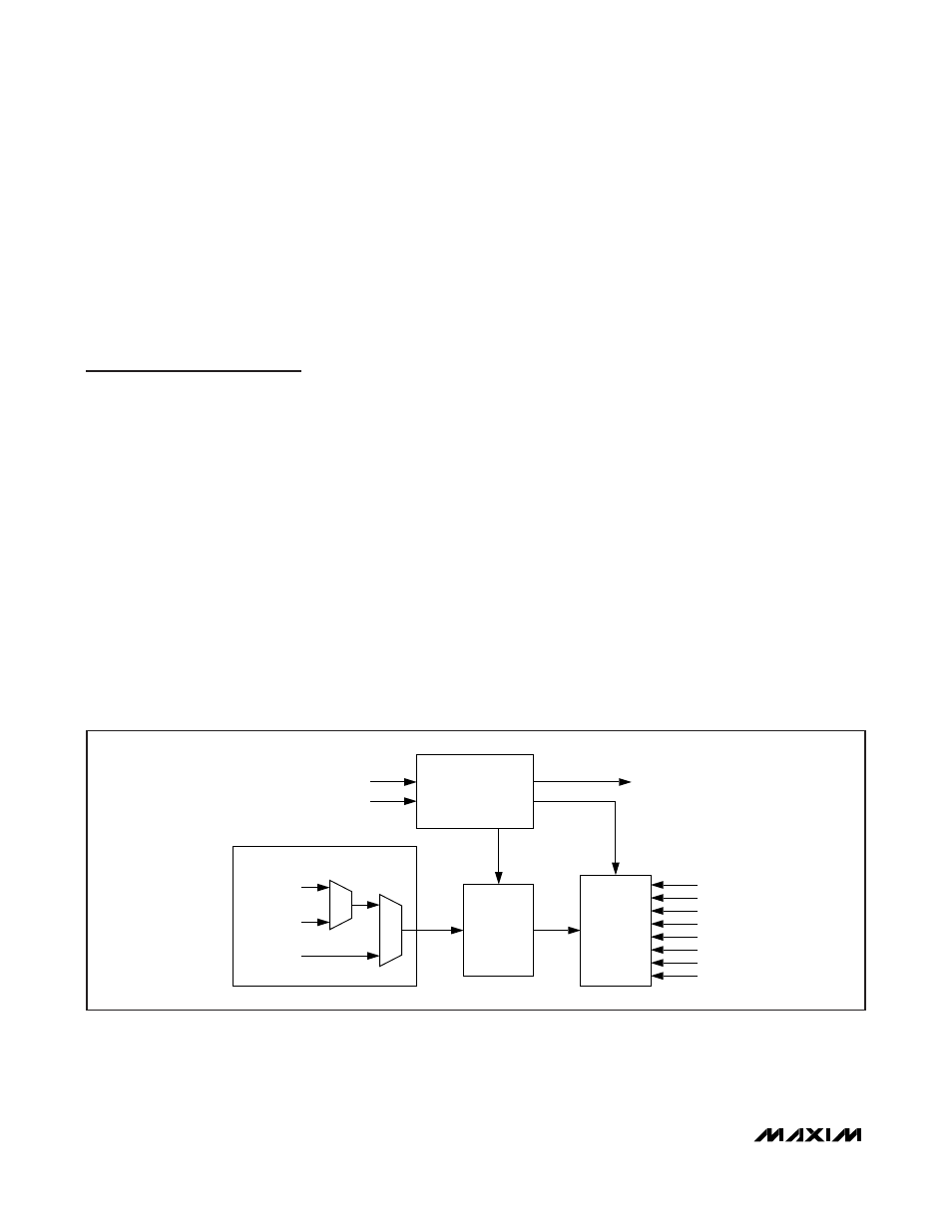
Figure 7. ADC Block Diagram