Pin description (continued) – Rainbow Electronics MAXQ2010 User Manual
Page 17
MAXQ2010
16-Bit Mixed-Signal Microcontroller with LCD
______________________________________________________________________________________
17
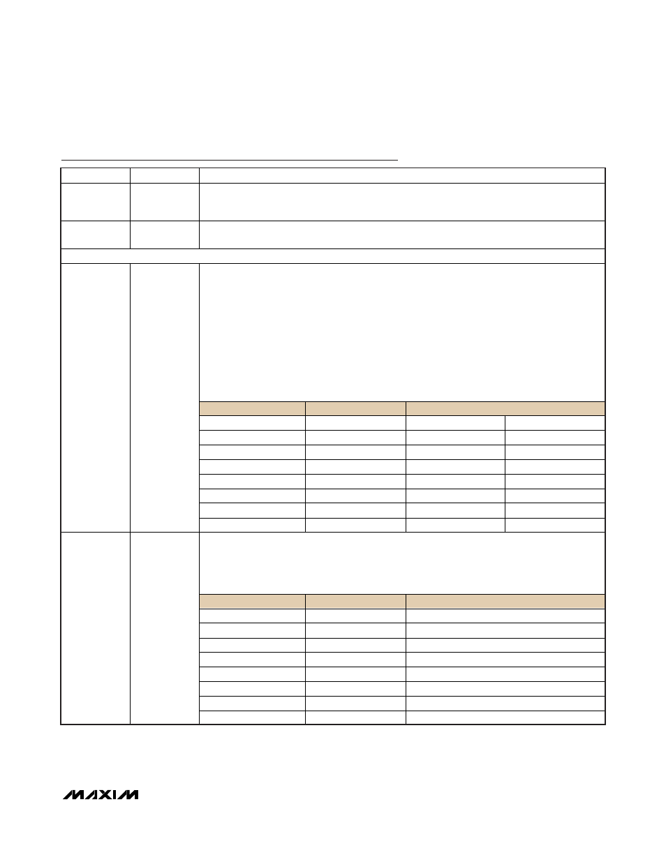
Pin Description (continued)
PIN
NAME
FUNCTION
43
V
LCD2
LCD Bias, Voltage 2. LCD drive voltage used with 1/3 LCD bias. An internal resistor-divider
sets the voltage. External resistors and capacitors can be used to change LCD voltage or
drive capability at this pin.
42
V
ADJ
LCD Adjustment Voltage. Connect to an external resistor to provide external control of the LCD
contrast. Leave disconnected for internal contrast adjustment.
GENERAL-PURPOSE I/O, SPECIAL FUNCTION, AND LCD INTERFACE PINS
Digital I/O, Type D Port 0; LCD Segment-Driver Output; External Edge-Selectable Interrupt.
This port functions as either bidirectional I/O or alternate LCD segment-drive outputs. The reset
condition of the port is with all bits at logic 1. In this state, a weak pullup holds the port high.
This condition serves as an input mode. Each port pin can individually be configured to act as
an external interrupt. Setting the PCF0 bit switches all pins on this port to LCD segment-drive
outputs.
It is possible to mix the LCD and interrupt functions on the same port. To do this, the interrupt
enable must be established prior to setting the PCF0 bit. Care must be taken not to enable the
external interrupt while the LCD is in normal operational mode, as this could result in
potentially harmful contention between the LCD controller output and the external source
connected to the interrupt input.
PIN
PORT
SPECIAL/ALTERNATE FUNCTION
6 P0.0
SEG0
INT0
5 P0.1
SEG1
INT1
4 P0.2
SEG2
INT2
3 P0.3
SEG3
INT3
2 P0.4
SEG4
INT4
1 P0.5
SEG5
INT5
94 P0.6
SEG6
INT6
6–1, 94, 93
P0.0–P0.7;
SEG0–SEG7;
INT0–INT7
93 P0.7
SEG7
INT7
Digital I/O, Type C Port 1; LCD Segment-Driver Output. This port functions as either
bidirectional I/O or alternate LCD segment-drive outputs. The reset condition of the port is with
all bits at logic 1. In this state, a weak pullup holds the port high. This condition serves as an
input mode. The port pins also contain a Schmitt voltage input. Setting the PCF1 bit switches
all pins on this port to LCD segment-drive outputs.
PIN
PORT
SPECIAL/ALTERNATE FUNCTION
91 P1.0
SEG8
90 P1.1
SEG9
89 P1.2
SEG10
88 P1.3
SEG11
87 P1.4
SEG12
86 P1.5
SEG13
85 P1.6
SEG14
91–84
P1.0–P1.7;
SEG8–SEG15
84 P1.7
SEG15