Supply voltage monitor, Serial peripherals, Figure 6. type c/d port pin schematic – Rainbow Electronics MAXQ2010 User Manual
Page 25
MAXQ2010
16-Bit Mixed-Signal Microcontroller with LCD
______________________________________________________________________________________
25
Supply Voltage Monitor
The supply voltage monitor can detect if the supply volt-
age has fallen below a user-selectable level. If this hap-
pens, the microcontroller can be programmed to
generate an interrupt to inform the system. The detec-
tion level is set using the supply voltage threshold bit
(SVMTH) and can be adjusted from 2.7V to 3.5V in 0.1V
increments. Setting the SVMEN bit to 1 enables the sup-
ply voltage monitor. Once the monitoring circuitry is sta-
ble and ready for operation, the supply voltage monitor
ready (SVMRDY) flag is set to 1. The default set point is
2.7V (SVTH[3:0] = 07h). Care must be taken not to set
the set point below 2.7V as SVM interrupts may not
occur because the brownout monitor may activate first.
The supply voltage monitor causes a switchback to
occur if the supply voltage falls below the threshold
value and the supply voltage monitor interrupt is
enabled (SVMIE = 1).
The supply voltage monitor remains operational in stop
mode if the supply voltage monitor stop mode enable
bit (SVMSTOP) is set to 1. Clearing SVMSTOP to 0 dis-
ables the supply voltage monitor on entry to stop mode
if the SVM peripheral is enabled. If the supply voltage
monitor is enabled during stop mode, an SVMI interrupt
causes the processor to exit stop mode if enabled
(SVMIE = 1).
Serial Peripherals
The microcontroller supports two independent USARTs
as well as I
2
C master/slave and SPI master communi-
cation ports.
USART Serial Ports
The independent USARTs provide transmit and receive
signals to communicate with other RS-232 interface-
enabled devices, as well as PCs and serial modems
when paired with an external RS-232 line driver/receiver.
The dual independent USARTs can communicate simulta-
neously at different baud rates with two separate periph-
erals. The USART can detect framing errors and indicate
the condition through a user-accessible software bit.
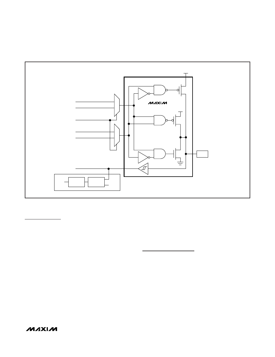
PD.x
SF DIRECTION
SF ENABLE
MUX
MUX
PO.x
V
DDIO
SF OUTPUT
V
DDIO
WEAK
I/O PAD
PORT PIN
INTERRUPT
FLAG
FLAG
PI.x OR SF INPUT
EIES.x
TYPE D PORT ONLY
DETECT
CIRCUIT
MAXQ2010
Figure 6. Type C/D Port Pin Schematic