Pin descriptions – Rainbow Electronics MAX13237E User Manual
Page 9
MAX13234E–MAX13237E
3Mbps RS-232 Transceivers with
Low-Voltage Interface
_______________________________________________________________________________________
9
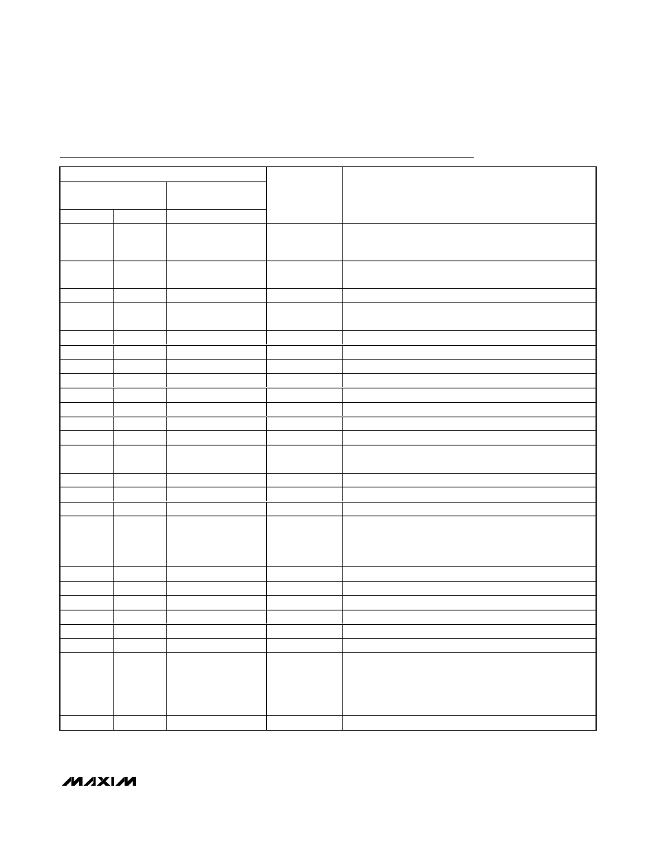
Pin Descriptions
PIN
MAX13234E/
MAX13235E
MAX13236E/
MAX13237E
TSSOP
TQFN-EP
TQFN-EP
NAME
FUNCTION
1
19
14
READY
Ready to Transmit Output, Active-High. READY is enabled
high when V- goes below -4V and the device is ready to
transmit.
2
1
16
C1+
Positive Terminal of the Voltage Doubler Charge-Pump
Capacitor
3
20
15
V+
+5.5V Generated by the Charge Pump
4
2
1
C1-
Negative Terminal of the Voltage Doubler Charge-Pump
Capacitor
5
3
2
C2+
Positive Terminal of the Inverting Charge-Pump Capacitor
6
4
3
C2-
Negative Terminal of the Inverting Charge-Pump Capacitor
7
5
4
V-
-5.5V Generated by the Charge Pump
8
6
—
T2OUT
RS-232 Transmitter Output 2
—
—
5
RIN
RS-232 Receiver Input
9
7
—
R2IN
RS-232 Receiver Input 2
—
—
6
ROUT
CMOS Receiver Output. V
L
referred logic.
10
8
—
R2OUT
CMOS Receiver Output 2. V
L
referred logic.
11
9
7
V
L
Logic-Level Supply. All CMOS inputs and outputs are related
to this supply.
—
—
8
TIN
CMOS Transmitter Input. V
L
referred logic.
12
10
—
T2IN
CMOS Transmitter Input 2. V
L
referred logic.
13
11
—
T1IN
CMOS Transmitter Input 1. V
L
referred logic.
14
12
9
FORCEON
FORCEON Input, Active-High. V
L
referenced logic. Drive
FORCEON high to override automatic circuitry keeping
transmitters on (
FORCEOFF must be high).
See Table 1.
15
13
—
R1OUT
CMOS Receiver Output 1. V
L
referred logic.
—
—
10
TOUT
RS-232 Transmitter Output
16
14
—
R1IN
RS-232 Receiver Input 1
17
15
—
T1OUT
RS-232 Transmitter Output 1
18
16
11
GND
Ground
19
17
12
V
CC
+3V to +5.5V Supply Voltage
20
18
13
FORCEOFF
FORCEOFF Input, Active-Low. V
L
referenced logic. Drive
FORCEOFF low to shut down transmitters and on-board
charge pumps. All receiver and transmitter outputs are tri-
stated. This overrides all automatic circuitry and FORCEON
(Table 1).
—
—
—
EP
Exposed Pad. Connect EP to GND or leave unconnected.