Detailed description – Rainbow Electronics MAX13237E User Manual
Page 10
MAX13234E–MAX13237E
3Mbps RS-232 Transceivers with
Low-Voltage Interface
10
______________________________________________________________________________________
Detailed Description
VL Logic Supply Input
The MAX13234E–MAX13237E feature a separate logic
supply input (V
L
) that sets the receiver’s output level
(V
OH
), and sets the transmitter’s input thresholds (V
IL
,
V
IH
). This feature allows flexibility in interfacing to
UARTs or communication controllers that have different
logic levels. Connect this input to the host logic supply
(1.62V ≤ V
L
≤ V
CC
).
Dual Charge-Pump Voltage Converter
The internal power supply consists of a regulated dual
charge pump that provides output voltages of +5.5V
and -5.5V (inverting charge pump), over the +3.0V to
+5.5V range. The charge pump operates in discontinu-
ous mode: if the output voltages are less than +5.5V,
the charge pump is enabled; if the output voltages
exceed +5.5V, the charge-pump is disabled. The
charge pumps require flying capacitors (C1, C2) and
reservoir capacitors (C3, C4) to generate the V+ and V-
supplies. The READY output is low when the charge
pumps are disabled in shutdown mode. The READY
signal asserts high when V- goes below -4V.
RS-232 Transmitters
The transmitters are inverting level translators that con-
vert CMOS-logic levels to ±5.0V EIA/TIA-232 levels.
The MAX13234E/MAX13236E guarantee a 250kbps
data rate with worst-case loads of 3kΩ in parallel with
1000pF. The MAX13235E/MAX13237E guarantee a
1Mbps data rate with worst-case loads of 3kΩ in paral-
lel with 250pF, and a 3Mbps data rate with worst-case
loads of 3kΩ in parallel with 150pF. Transmitters can be
paralleled to drive multiple receivers. When
FORCEOFF
is driven to ground or when the AutoShutdown Plus cir-
cuitry senses that all receiver and transmitter inputs are
inactive for more than 30s, the transmitters are disabled
and the outputs go into a high-impedance state. When
powered off or shut down, the outputs can be driven to
±12V. The transmitter inputs do not have pullup resis-
tors. Connect unused inputs to GND or V
L
.
RS-232 Receivers
The receivers convert RS-232 signals to CMOS-logic
output levels. The MAX13234E–MAX13237E have
inverting outputs that are active when in shutdown
(
FORCEOFF = GND) (Table 1).
AutoShutdown Plus Mode
Drive
FORCEOFF high and FORCEON low to invoke
AutoShutdown Plus mode. When these devices do not
sense a valid signal transition on any receiver and
transmitter input for 30s, the onboard charge pumps
are shut down, reducing supply current to 1µA. This
occurs if the RS-232 cable is disconnected or
if the devices driving the transmitter and receiver
inputs are inactive for more than 30s. The
MAX13234E–MAX13237E turn on again when a valid
transition is applied to any RS-232 receiver or transmit-
ter input. As a result, the system saves power without
requiring any control.
Figure 6 and Table 1 summarize the MAX13234E–
MAX13237E operating modes. The FORCEON and
FORCEOFF inputs override AutoShutdown Plus circuit-
ry. When neither control is asserted, the IC selects
between these states automatically based on the last
receiver or transmitter input edge received.
Hardware-Controlled Shutdown
Drive
FORCEOFF low to place the MAX13234E–
MAX13237E into shutdown mode.
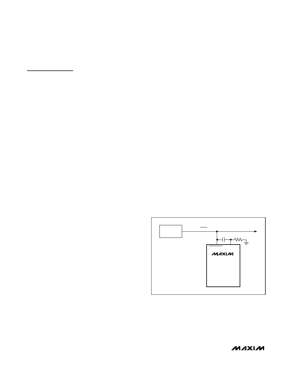
FORCEON
MASTER SHDN LINE
0.1
μF
1M
Ω
FORCEOFF
MAX13234E
MAX13235E
MAX13236E
MAX13237E
POWER-
MANAGEMENT
UNIT
Figure 7. AutoShutdown Plus Initial Turn-On to Wake Up a
Mouse or Another System