Electrical characteristics (continued) – Rainbow Electronics MAX13237E User Manual
Page 4
MAX13234E–MAX13237E
3Mbps RS-232 Transceivers with
Low-Voltage Interface
4
_______________________________________________________________________________________
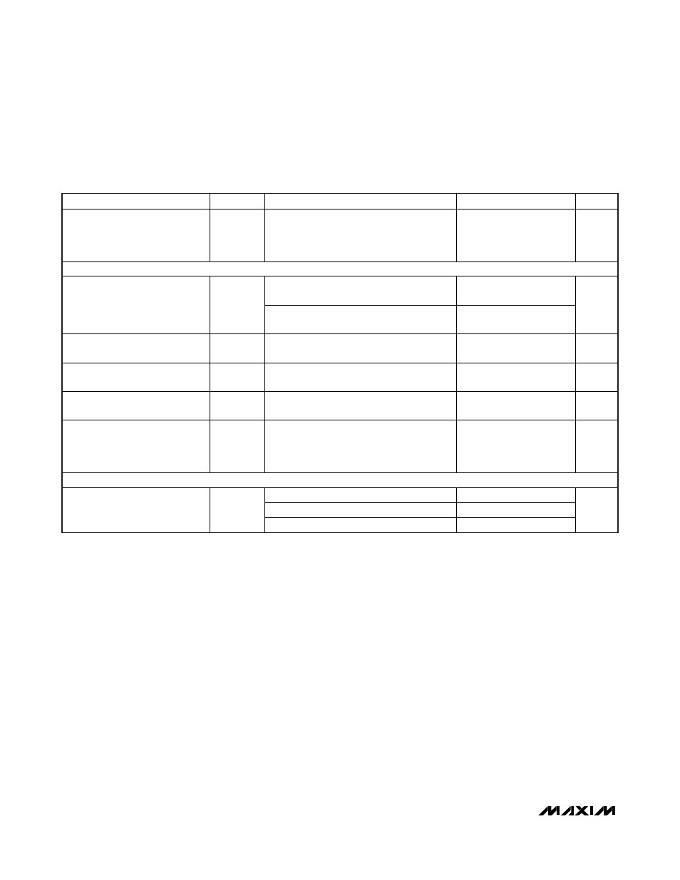
ELECTRICAL CHARACTERISTICS (continued)
(V
CC
= +3V to +5.5V, V
L
= +1.62V to V
CC
, T
A
= -40°C to +85°C, C1–C4 = 0.1µF, V
CC
= V
L
, tested at 3.3V ±10%. Typical values are
at TA = +25°C.) (Note 2)
PARAMETER
SYMBOL
CONDITIONS
MIN
TYP
MAX
UNITS
Transition-Region Slew Rate
V
CC
= +3.3V, T
A
= +25°C, R
L
= 3k
Ω to 7kΩ,
measured from +3V to -3V or -3V to +3V,
one transmitter switching, C
L
= 150pF to
1000pF
6
30
V/µs
TIMING CHARACTERISTICS (MAX13235E/MAX13237E)
R
L
= 3k
Ω, C
L
= 250pF, one transmitter
switching
1
Maximum Data Rate
R
L
= 3k
Ω, C
L
= 150pF, one transmitter
switching
3
Mbps
Receiver Propagation Delay
t
RPHL
,
t
RPLH
C
L
= 150pF, Figures 2, 3
0.15
µs
Transmitter Skew
|t
TPHL
–
t
TPLH
|
Figures 4, 5 (Note 4)
25
ns
Receiver Skew
|t
RPHL
–
t
RPLH
|
Figures 2, 3
50
ns
Transition-Region Slew Rate
V
CC
= +3.3V, T
A
= +25°C, R
L
= 3k
Ω to 7kΩ,
measured from T
_OUT
= +3V to -3V or -3V
to +3V, one transmitter switching, C
L
=
150pF to 1000pF
24
150
V/µs
ESD PROTECTION
Human Body Model
±15
IEC 61000-4-2 Air Discharge
±15
R_IN, T_OUT to GND
IEC 61000-4-2 Contact Discharge
±8
kV
Note 2: All devices are 100% production tested at T
A
= +85°C. All temperature limits are guaranteed by design.
Note 3: A transmitter/receiver edge is defined as a transition through the transmitter/receiver input-logic thresholds.
Note 4: Transmitter skew is measured at the transmitter zero cross points.