Test circuits/timing diagram (continued) – Rainbow Electronics MAX13237E User Manual
Page 6
MAX13234E–MAX13237E
3Mbps RS-232 Transceivers with
Low-Voltage Interface
6
_______________________________________________________________________________________
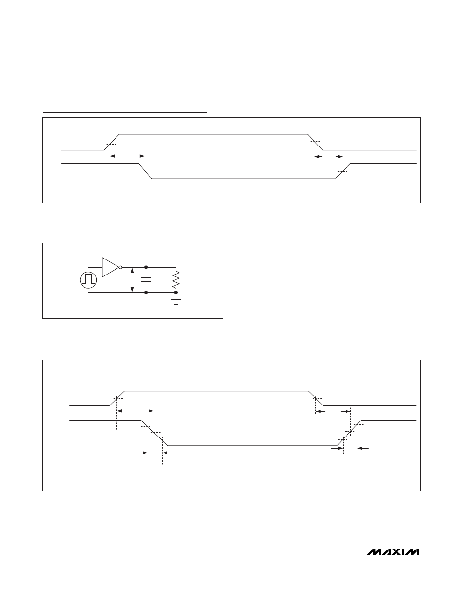
Test Circuits/Timing Diagram (continued)
0
t
TPHL
0
V
O
-V
O
T_IN
T_OUT
-3V
3V
t
F
0
t
TPLH
3V
-3V
t
R
SR
F
= 6/t
F
SR
R
= 6/t
R
V
L
/2
V
L
/2
V
L
t
R
, t
F
≤ 10ns
Figure 5. Transmitter Propagation Delay
C
L
T_OUT
T_IN
R
L
V
O
Figure 4. Transmitter Test Circuit
V
OH
V
OL
R_IN
R_OUT
1.3V
t
RPHL
1.7V
t
RPLH
t
R
, t
F
≤ 10ns
V
L
/2
V
L
/2
Figure 3. Receiver Propagation Delay
See also other documents in the category Rainbow Electronics Control panel:
- MAX16840 (1 page)
- MAX9258 (54 pages)
- MAX66140 (21 pages)
- MAX9393 (14 pages)
- MAX66040 (25 pages)
- MAX6981 (1 page)
- MAX6965 (23 pages)
- MAX66100 (16 pages)
- MAX9135 (19 pages)
- MAX66020 (25 pages)
- MAX17127 (22 pages)
- MAX13175E (38 pages)
- MAX16820 (10 pages)
- MAX13483E (19 pages)
- MAX13362 (14 pages)
- MAX13486E (16 pages)
- MAX7311 (17 pages)
- MAX8759 (31 pages)
- SCAN92LV090 (13 pages)
- MAX6973 (23 pages)
- MAX13047E (14 pages)
- MAX16831 (20 pages)
- MAX14770E (15 pages)
- MAX11835 (1 page)
- MAX9621 (14 pages)
- MAX9217 (16 pages)
- MAX16841 (18 pages)
- MAX16834 (22 pages)
- MAX7315 (27 pages)
- MAX8645Y (15 pages)
- MAX6975 (23 pages)
- MAX6971 (12 pages)
- MAX3028 (21 pages)
- MAX9395 (13 pages)
- MAX7313 (27 pages)
- MAX6970 (1 page)
- MAX4821 (13 pages)
- MAX4895E (8 pages)
- MAX16823 (13 pages)
- MAX6963 (34 pages)
- MAX9216 (17 pages)
- MAX66000 (21 pages)
- MAX66120 (24 pages)
- MAX13223E (11 pages)