Pin description pin configuration – Rainbow Electronics MAX17127 User Manual
Page 9
_______________________________________________________________________________________ 9
MAX17127
Six-String WLED Driver with Integrated
Step-Up Converter
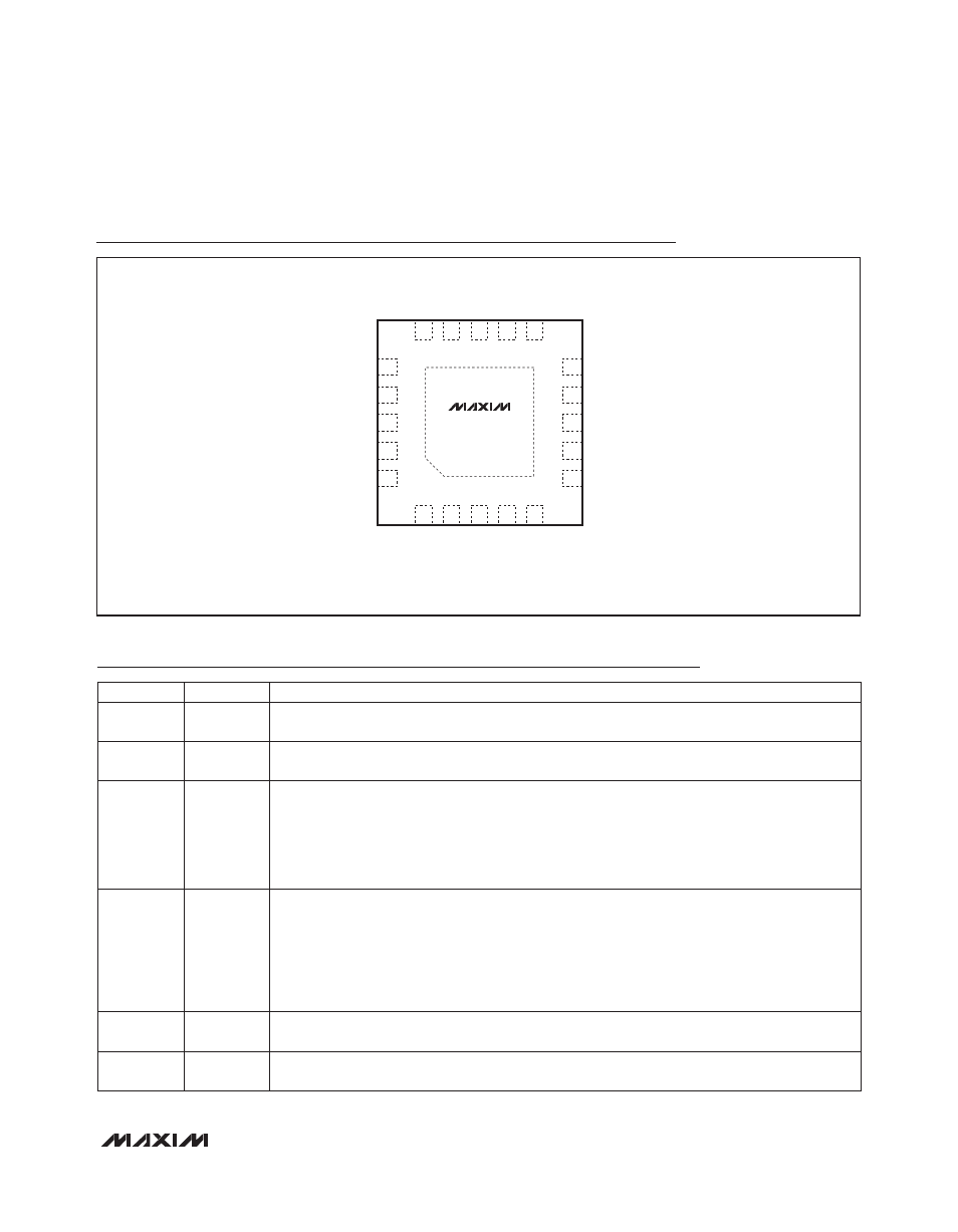
Pin Description
Pin Configuration
19
20
18
17
7
6
8
EN
FPO
9
V
DDIO
OVP
FB1
FB2
PGND
1
2
COMP
4
5
15
14
12
11
V
IN
PWM
+
EP
AGND
FB4
FB5
FB6
FSLCT
R_FPWM
3
13
I.C.
16
10 FB3
SW
THIN QFN
(4mm × 4mm)
TOP VIEW
ISET
MAX17127
PIN
NAME
FUNCTION
1
V
DDIO
5V Linear Regulator Output. V
DDIO
provides power to the MAX17127. Bypass V
DDIO
to AGND with
a ceramic capacitor of 1FF or greater.
2
EN
Enable Pin. EN = high enables the MAX17127. An internal 200kI (typ) pulldown resistor keeps the
MAX17127 in disabled mode if the EN pin is high impedance.
3
FSLCT
Oscillator Frequency-Adjustment Pin. The resistance from FSLCT to AGND sets the step-up
converter’s oscillator frequency:
f
SW
= 1MHz O 100kI/R
FSLCT
The acceptable resistance range is 100kI < R
FSLCT
< 400kI, which corresponds to the switching
frequency of 1MHz > f
SW
> 250kHz.
4
ISET
Full-Scale LED Current-Adjustment Pin. The resistance from ISET to AGND controls the full-scale
current in each LED string:
I
LEDMAX
= 20mA O 180kI/R
ISET
The acceptable resistance range is 120kI < R
ISET
< 360kI, which corresponds to a full-scale LED
current of 30mA > I
LEDMAX
> 10mA. Connecting ISET to AGND sets the test mode for 0.3mA (typ)
full-scale LED current.
5
FPO
Fault-Diagnostic Output. Open drain, active low. The FPO output is asserted low when the following
faults occur: overcurrent fault, thermal fault, output-voltage short condition, or output overvoltage.
6
FB6
LED String 6 Cathode Connection. FB6 is the open-drain output of an internal regulator, which
controls current through FB6. FB6 can sink up to 30mA. If unused, connect FB6 to AGND.