Rainbow Electronics MAX66020 User Manual
Page 7
MAX66020
ISO/IEC 14443 Type B-Compliant
1Kb Memory Fob
_______________________________________________________________________________________
7
ISO/IEC 14443 Type B
Communication Concept
The communication between the master and the
MAX66020 (slave) is based on the exchange of data
packets. The master initiates every transaction; only
one side (master or slaves) transmits information at any
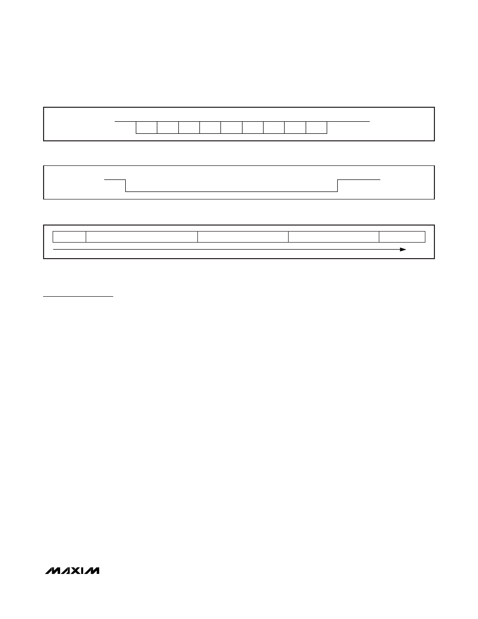
time. Data packets are composed of characters, which
always begin with a START bit and typically end with
one or more STOP bits (Figure 5). The least significant
data bit is transmitted first. Data characters have 8 bits.
Each data packet begins with a start-of-frame (SOF)
character and ends with an end-of-frame (EOF) charac-
ter. The EOF/SOF characters have 9 all-zero data bits
(Figure 6). The SOF has 2 STOP bits, after which data
characters are transmitted. A data packet with at least
3 bytes between SOF and EOF is called a frame
(Figure 7). The last two data characters of an
ISO/IEC 14443 Type B frame are an inverted 16-bit
CRC of the preceding data characters generated
according to the CRC-16-CCITT polynomial. This CRC
is transmitted with the LSB first. For more details on the
CRC-16-CCITT, refer to ISO/IEC 14443-3, Annex B.
With network function commands, the command code,
parameters, and response are embedded between
SOF and CRC. With memory function commands, com-
mand code, and parameters are placed into the infor-
mation field of I-blocks (see the
Block Types
section),
which in turn are embedded between SOF and EOF.
For transmission, the frame information is modulated on a
carrier frequency, which is 13.56MHz for ISO/IEC 14443 .
The subsequent paragraphs are a concise description
of the required modulation and coding. For full details
including SOF/EOF and subcarrier on/off timing, refer to
ISO/IEC 14443-3, Sections 7.1 and 7.2.
The path from master to slave uses amplitude modula-
tion with a modulation index between 8% and 14%
(Figure 8). In this direction, a START bit and logic 0 bit
correspond to a modulated carrier; STOP bit and
logic 1 bit correspond to the unmodulated carrier. EOF
ends with an unmodulated carrier instead of STOP bits.
The path from slave to master uses an 847.5kHz sub-
carrier, which is modulated using binary phase-shift key
(BPSK) modulation. Depending on the data rate, the
transmission of a single bit takes eight, four, two, or one
subcarrier cycles. The slave generates the subcarrier
only when needed; i.e., starting shortly before an SOF
and ending shortly after an EOF. The standard defines
the phase of the subcarrier before the SOF as 0° refer-
ence, which corresponds to logic 1. The phase of the
subcarrier changes by 180° whenever there is a binary
transition in the character to be transmitted (Figure 9).
The first phase transition represents a change from
logic 1 to logic 0, which coincides with the beginning of
the SOF. The BPSK modulated subcarrier is used to
modulate the load on the fob’s antenna (Figure 10).
START
1
0
BIT 1
BIT 2
BIT 3
BIT 4
BIT 5
BIT 6
BIT 7
BIT 8
LSb
MSb
STOP
Figure 5. ISO/IEC 14443 Data Character Format
START
1
0
BIT 1
BIT 2
BIT 3
BIT 4
BIT 5
BIT 6
BIT 7
BIT 9
STOP/IDLE
BIT 8
Figure 6. ISO/IEC 14443 SOF/EOF Character Format
SOF
ONE OR MORE DATA CHARACTERS
CRC (LSB)
CRC (MSB)
EOF
TIME
Figure 7. ISO/IEC 14443 Frame Format