Detailed description – Rainbow Electronics MAX66020 User Manual
Page 3
MAX66020
ISO/IEC 14443 Type B-Compliant
1Kb Memory Fob
_______________________________________________________________________________________
3
Detailed Description
The MAX66020 combines 1024 bits of user EEPROM,
128 bits of user and control registers, a 64-bit UID, and
a 13.56MHz RF interface (ISO/IEC 14443 Type B, Parts
2-4) in a single key fob. The memory is organized as 18
blocks of 8 bytes each. Four adjacent user EEPROM
blocks form a memory page (pages 0 to 3). Memory
protection features include write protection and EPROM
emulation, which the user can set for each individual
memory page. The memory of the MAX66020 is
accessed through the ISO/IEC 14443-4 block transmis-
sion protocol, where requests and responses are
exchanged through I-blocks once a device is in the
ACTIVE state. The reader must support a frame size of
at least 19 bytes. The data rate can be as high as
847.5kbps. The MAX66020 supports AFI and CID.
Functions not supported are chaining, frame-waiting
time extension, and power indication. Applications of
the MAX66020 include driver identification (fleet appli-
cation), access control, and asset tracking.
Overview
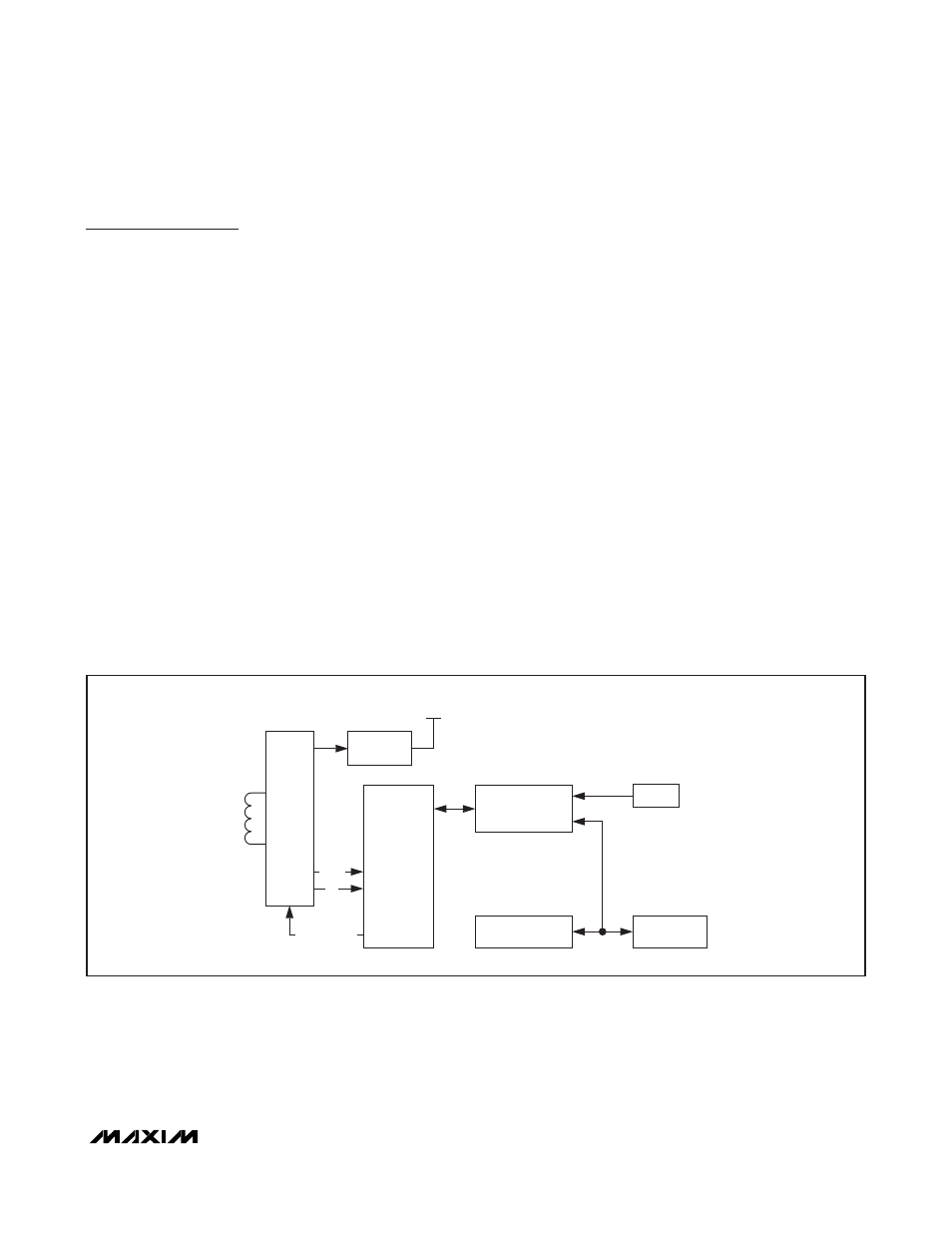
Figure 1 shows the relationships between the major
control and memory sections of the MAX66020. The
device has three main data components: 64-bit UID,
four 256-bit pages of user EEPROM, and two 8-byte
blocks of user and control registers. Figure 2 shows the
hierarchical structure of the ISO/IEC 14443 Type B-
compliant access protocol. The master must first apply
network function commands to put the MAX66020 into
the ACTIVE state before the memory and control func-
tions become accessible. The protocol required for
these network function commands is described in the
Network Function Commands
section. Once the
MAX66020 is in the ACTIVE state, the master can issue
any one of the available memory and control function
commands. Upon completion of such a command, the
MAX66020 returns to the ACTIVE state and the master
can issue another memory and control function com-
mand or deselect the device, which returns it to the
HALT state. The protocol for these memory and control
function commands is described in the
Memory and
Control Function Commands
section. All data is read
and written least significant bit (LSb) first, starting with
the least significant byte (LSB).
Parasite Power
As a wireless device, the MAX66020 is not connected
to any power source. It gets the energy for operation
from the surrounding RF field, which needs to have a
minimum strength as specified in the
Electrical
Characteristics
table.
RF
FRONT-
END
VOLTAGE
REGULATOR
INTERNALSUPPLY
MEMORY AND
FUNCTION
CONTROL
ISO 14443
FRAME
FORMATTING
AND
ERROR
DETECTION
UID
REGISTER
BLOCK
USER
EEPROM
f
c
DATA
MODULATION
Figure 1. Block Diagram