Rainbow Electronics MAX66020 User Manual
Page 5
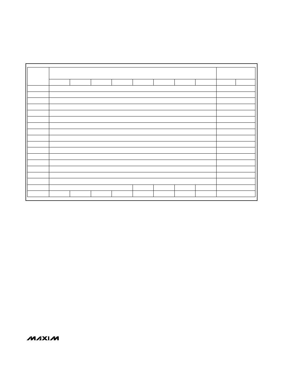
Block 10h provides storage for user-programmable
parameters that are defined by the ISO/IEC 14443 stan-
dard. These are application data field and AFI. The
remaining bytes (U1, U2, U3) are not defined by the
communication standard; the application software can
use them, e.g., for proprietary markings. Block 11h con-
tains control bytes that determine the operation of the
individual pages (EPROM-emulation mode, write protec-
tion of individual blocks), or to write protect the applica-
tion data field, the AFI, and U1. The S-Lock byte, if
programmed to a suitable code, only protects itself from
future changes. The self-protection feature can be used
to permanently mark the fob as being “special,” as
defined by the application. Table 1 illustrates the rela-
tionship between the controlling register in block 11h
and the memory area affected. Tables 2 and 3 specify
the code assignments to achieve the protection.
Besides the storage for 8 data bytes, each memory
block has 2 integrity bytes, which are not memory
mapped. The integrity bytes function as a MAX66020-
m a i n t a i n e d , 1 6 - b i t w r i t e - c y c l e c o u n t e r . H a v i n g
reached its maximum value of 65,535, the write-cycle
counter stops incrementing, but does not prevent
additional write cycles to the memory block. The
integrity bytes can be read through the Custom Read
Block command.
MAX66020
ISO/IEC 14443 Type B-Compliant
1Kb Memory Fob
_______________________________________________________________________________________
5
DATA BYTE NUMBER
(SEQUENCE LEFT TO RIGHT AS WRITTEN TO OR READ FROM DEVICE)
INTEGRITY BYTES
BLOCK
NUMBER
0 1 2 3 4 5 6 7
LSB
MSB
00h
Page 0 User EEPROM R/(W)
Write-Cycle Counter
01h
Page 0 User EEPROM R/(W)
Write-Cycle Counter
02h
Page 0 User EEPROM R/(W)
Write-Cycle Counter
03h
Page 0 User EEPROM R/(W)
Write-Cycle Counter
04h
Page 1 User EEPROM R/(W)
Write-Cycle Counter
05h
Page 1 User EEPROM R/(W)
Write-Cycle Counter
06h
Page 1 User EEPROM R/(W)
Write-Cycle Counter
07h
Page 1 User EEPROM R/(W)
Write-Cycle Counter
08h
Page 2 User EEPROM R/(W)
Write-Cycle Counter
09h
Page 2 User EEPROM R/(W)
Write-Cycle Counter
0Ah
Page 2 User EEPROM R/(W)
Write-Cycle Counter
0Bh
Page 2 User EEPROM R/(W)
Write-Cycle Counter
0Ch
Page 3 User EEPROM R/(W)
Write-Cycle Counter
0Dh
Page 3 User EEPROM R/(W)
Write-Cycle Counter
0Eh
Page 3 User EEPROM R/(W)
Write-Cycle Counter
0Fh
Page 3 User EEPROM R/(W)
Write-Cycle Counter
10h
ISO/IEC 14443 Application Data Field
AFI
U1
U2
U3
Write-Cycle Counter
11h BP1 BP2 BP3 BP4
ADF-Lock
AFI-Lock
U1-Lock
S-Lock
Write-Cycle
Counter
Figure 4. Memory Map