Rainbow Electronics MAX66020 User Manual
Page 4
MAX66020
ISO/IEC 14443 Type B-Compliant
1Kb Memory Fob
4
_______________________________________________________________________________________
AVAILABLE COMMANDS:
DATA FIELD AFFECTED:
REQUEST (REQB)
WAKEUP (WUPB)
SLOT-MARKER
HALT (HLTB)
SELECT (ATTRIB)
DESELECT (DESELECT)
AFI, ADMINISTRATIVE DATA
AFI, ADMINISTRATIVE DATA
(ADMINISTRATIVE DATA)
PUPI
PUPI, ADMINISTRATIVE DATA
(ADMINISTRATIVE DATA)
NETWORK
FUNCTION COMMANDS
GET SYSTEM INFORMATION
WRITE SINGLE BLOCK
LOCK BLOCK
READ SINGLE BLOCK
READ SINGLE BLOCK WITH
BLOCK SECURITY STATUS
CUSTOM READ BLOCK
WRITE AFI
LOCK AFI
GET UID
64-BIT UID, AFI, CONSTANTS
DATA OF SELECTED MEMORY BLOCK, APPLICABLE PROTECTION CONTROL REGISTER
PROTECTION CONTROL REGISTER
SELECTED MEMORY BLOCK
SELECTED MEMORY BLOCK, APPLICABLE PROTECTION CONTROL REGISTER
SELECTED MEMORY BLOCK, INTEGRITY BYTES
AFI BYTE
AFI-LOCK BYTE
64-BIT UID
MEMORY AND CONTROL
FUNCTION COMMANDS
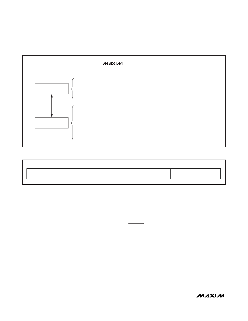
COMMAND LEVEL:
MAX66020
Figure 2. Hierarchical Structure of ISO/IEC 14443 Type B Protocol
MSb
LSb
64
57 56
49 48
45 44
37 36
1
E0h
2Bh
0h
FEATURE CODE (02h)
36-BIT IC SERIAL NUMBER
Figure 3. 64-Bit UID
Unique Identification Number (UID)
Each MAX66020 contains a factory-programmed and
locked identification number that is 64 bits long
(Figure 3). The lower 36 bits are the serial number of
the chip. The next 8 bits store the device feature
code, which is 02h. Bits 45 to 48 are 0h. The code in
bit locations 49 to 56 identifies the chip manufacturer,
according to ISO/IEC 7816-6/AM1. This code is 2Bh
for Maxim. The code in the upper 8 bits is E0h. The
UID is read accessible through the Get UID and Get
System Information commands. The lower 32 bits of
the UID are transmitted in the PUPI field of the ATQB
response to the REQB, WUPB, or SLOT-MARKER
command. By default, the upper 32 bits of the UID are
factory programmed into the application data field,
which is transmitted as part of the ATQB response.
This way the master receives the complete UID in the
first response from the slave. See the
Network
Function Commands
section for details.
Detailed Memory Description
The memory of the MAX66020 is organized as 18
blocks of 8 bytes each. Figure 4 shows the memory
map. The first 16 blocks (block numbers 00h to 0Fh in
hexadecimal counting) are the user EEPROM, the area
for application-specific data. Four adjacent blocks are
referred to as a page. Blocks 00h to 03h are page 0,
blocks 04h to 07h are page 1, blocks 08h to 0Bh are
page 2, and blocks 0Ch to 0Fh are page 3.