Electrical characteristics (continued) – Rainbow Electronics MAX8707 User Manual
Page 3
MAX8707
Multiphase, Fixed-Frequency Controller for
AMD Hammer CPU Core Power Supplies
_______________________________________________________________________________________
3
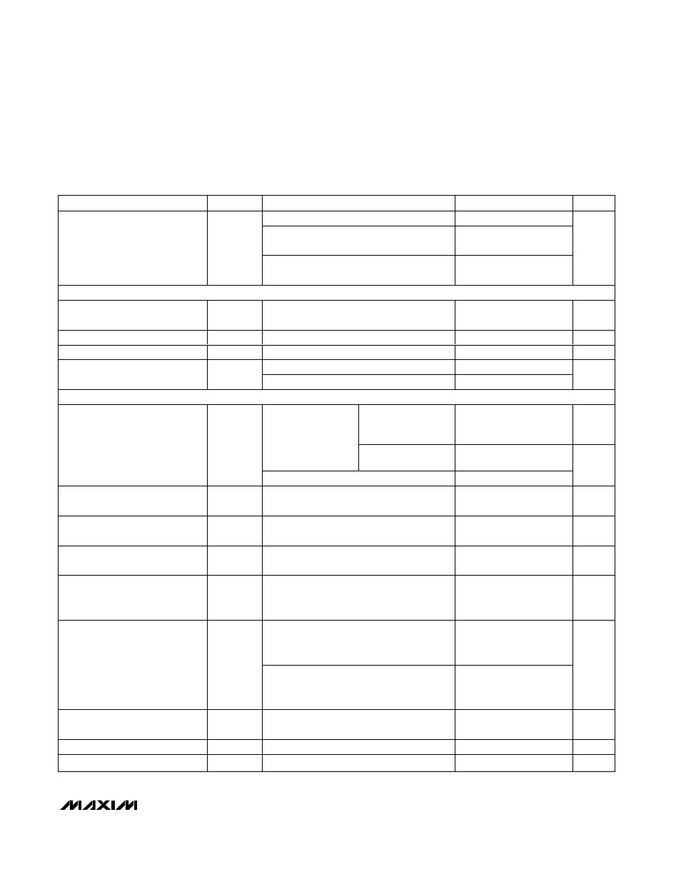
ELECTRICAL CHARACTERISTICS (continued)
(Circuit of Figure 1. V
CC
= V
SHDN
= 5V, OSC = REF, V
VPS
= V
FBS
= V
CRSN
= V
CRSP
= V
CSP_
= 1.20V, V
SUSV
= 0.8V, OFS = SUS =
GNDS = PGND = SKIP = GND, D0–D4 set for 1.20V (D0–D4 = 01110). T
A
= 0°C to +85°C, unless otherwise specified. Typical values
are at T
A
= +25°C.)
PARAMETER
SYMBOL
CONDITIONS
MIN
TYP
MAX
UNITS
R
TIME
= 143k
Ω (6.25mV/µs)
-10
+10
R
TIME
= 47k
Ω (19mV/µs) to 392kΩ
(2.28mV/µs)
-15
+15
TIME Slew-Rate Accuracy
Startup and shutdown, R
TIME
= 47k
Ω
(4.75mV/µs) to 392k
Ω (0.57mV/µs)
-20
+20
%
BIAS AND REFERENCE
Quiescent Supply Current (V
CC
)
I
CC
Measured at V
CC
, VPS and FBS forced
above the regulation points
7
12
mA
Shutdown Supply Current (V
CC
)
I
CC(SHDN)
Measured at V
CC
, SHDN = GND
0.05
10
µA
Reference Voltage
V
REF
V
CC
= 4.5V to 5.5V, I
REF
= 0
1.986
2.000
2.014
V
I
REF
= 0 to 500µA
-2
-0.2
Reference Load Regulation
∆V
REF
I
REF
= -100µA to 0
0.21
6.2
mV
FAULT PROTECTION
PWM (SKIP = GND)
or SKIP mode when
V
OUT
≤ V
TRIP
150
200
250
mV
Measured at VPS
with respect to
unloaded output
voltage, rising edge,
8mV hysteresis
SKIP = V
CC
and
V
OUT
> V
TRIP
1.70
1.75
1.80
Output Overvoltage-Protection
Threshold
V
OVP
Minimum OVP level
1.1
V
Output Overvoltage Propagation
Delay
t
OVP
VPS forced 25mV above trip threshold
10
µs
Output Undervoltage-Protection
Threshold
V
UVP
Measured at VPS with respect to 70% of the
unloaded nominal output voltage
-30
+30
mV
Output Undervoltage
Propagation Delay
t
UVP
VPS forced 25mV below trip threshold
10
µs
VROK Transition Blanking Time
t
BLANK
Measured from the time when VPS reaches
the target voltage, slew rate set by R
TIME
(Note 2)
20
µs
Undervoltage measured at VPS with
respect to 87.5% unloaded output voltage,
falling edge, 15mV hysteresis
-30
+30
VROK Threshold
Overvoltage measured at VPS with respect
to 112.5% of the unloaded output voltage,
rising edge, 15mV hysteresis
-30
+30
mV
VROK Delay
t
VROK
VPS forced 25mV outside the VROK trip
thresholds
10
µs
VROK Output Low Voltage
I
SINK
= 3mA
0.4
V
VROK Leakage Current
High state, VROK forced to 5.5V
1
µA