Table 5. skip settings – Rainbow Electronics MAX8707 User Manual
Page 26
MAX8707
Multiphase, Fixed-Frequency Controller for
AMD Hammer CPU Core Power Supplies
26
______________________________________________________________________________________
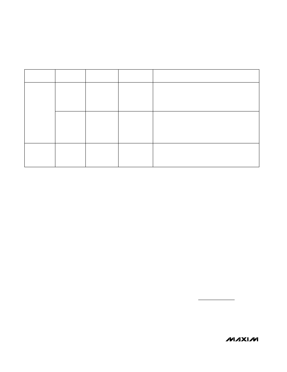
SKIP
(INPUT)
SUS
(INPUT)
MODE
DRSKP
(OUTPUT)
OPERATION
Low
(GND)
Multiphase
Forced-PWM
High
(V
DD
)
The controller operates with a constant switching
frequency, providing low-noise forced-PWM operation. The
controller disables the zero-crossing comparators, forcing
the low-side gate-drive waveform to constantly be the
complement of the high-side gate-drive waveform.
Low
(GND)
High
(3.3V or V
CC
)
1-Phase Pulse
Skipping
Low
(PGND)
The controller automatically switches to pulse-skipping
operation 20µs after the target voltage reaches the SUSV
voltage. Pulse-skipping operation forces the controller into
PFM operation under light loads. Phase 1 remains active
while the other three phases are disabled—PWM2, PWM3,
and PWM4 pulled low.
High
(>1.2V)
Don’t Care
1-Phase Pulse
Skipping
Low
(PGND)
Pulse-skipping operation forces the controller into PFM
operation under light loads. Phase 1 remains active while
the other three phases are disabled—PWM2, PWM3, and
PWM4 pulled low.
Table 5. SKIP Settings
Idle Mode is a trademark of Maxim Integrated Products, Inc.
sense voltage exceeds the Idle Mode
current-sense
threshold (V
IDLE
= 0.1 x V
PKLIMIT
). Under heavy-load
conditions, the continuous inductor current remains
above the Idle-Mode current-sense threshold, so the
on-time depends only on the feedback-voltage thresh-
old. Under light-load conditions, the controller remains
above the feedback-voltage threshold, so the on-time
duration depends solely on the Idle-Mode current-
sense threshold, which is approximately 10% of the full-
load current-limit threshold set by ILIM(PK).
When the controller enters suspend mode while SKIP is
pulled high, the multiphase controller immediately dis-
ables three phases, and only the main phase (PWM1)
remains active. When pulse skipping, the controller
blanks the upper VROK threshold and the OVP threshold
tracks the selected VID DAC code. The MAX8707 auto-
matically uses forced-PWM operation during soft-start
and soft-shutdown, regardless of the SKIP configuration.
Idle-Mode Current Sense Threshold
The Idle-Mode current-sense threshold forces a lightly
loaded regulator to source a minimum amount of ener-
gy with each on-time since the controller cannot termi-
nate the on-time until the current-sense voltage
exceeds the Idle-Mode current-sense threshold (V
IDLE
= 0.1 x V
PKLIMIT
). Since the zero-crossing comparator
prevents the switching regulator from sinking current,
the controller must skip pulses to avoid overcharging
the output. When the clock edge occurs, if the output
voltage still exceeds the feedback threshold, the con-
troller does not initiate another on-time. This forces the
controller to actually regulate the valley of the output
voltage ripple under light-load conditions.
Automatic Pulse-Skipping Crossover
In skip mode, the MAX8707 disables three phases and
forces DRSKP low to instruct the skip-mode drivers to
activate their zero-crossing comparators. Therefore, an
inherent automatic switchover to PFM takes place at light
loads (
Figure
6), resulting in a highly efficient operating
mode. This switchover is affected by a comparator that
truncates the low-side switch on-time at the inductor cur-
rent’s zero crossing. The driver’s zero-crossing compara-
tor senses the inductor current across the low-side
MOSFET (refer to the skip-mode driver data sheet).
Once V
LX
- V
PGND
drops below the zero-crossing
threshold, the driver forces DL low. This mechanism
causes the threshold between pulse-skipping PFM and
nonskipping PWM operation to coincide with the bound-
ary between continuous and discontinuous inductor-cur-
rent operation (also known as the critical conduction
point). The load-current level at which the PFM/PWM
crossover occurs, I
LOAD(SKIP)
, is given by:
The switching waveforms may appear noisy and asyn-
chronous when light loading causes pulse-skipping
operation, but this is a normal operating condition that
I
V
V
V
V f
L
LOAD SKIP
OUT
IN
OUT
IN SW
(
)
=
−
(
)
2