Pin description (continued) – Rainbow Electronics MAX8707 User Manual
Page 14
MAX8707
Multiphase, Fixed-Frequency Controller for
AMD Hammer CPU Core Power Supplies
14
______________________________________________________________________________________
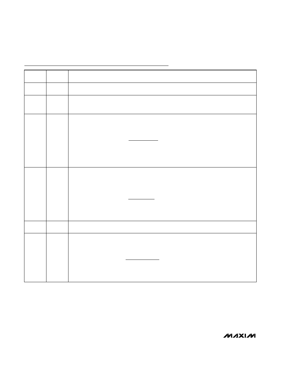
Pin Description (continued)
PIN
NAME
FUNCTION
11
OSC
Oscillator Select Input. OSC is a 3-level logic input for selecting the per-phase switching frequency.
Connect to GND for 200kHz, connect to REF for 300kHz, or connect to V
CC
for 600kHz per phase.
12
GNDS
Ground Remote-Sense Input. Connect GNDS directly to the CPU ground-sense pin. GNDS internally
connects to an amplifier that adjusts the output voltage, compensating for voltage drops from the regulator
ground to the load ground.
13
TIME
Slew-Rate Adjustment Pin. Connect a resistor from TIME to GND to set the internal slew rate. A 47k
Ω to
392k
Ω corresponds to slew rates of 19mV/µs to 2.28mV/µs, respectively, for all suspend voltage
transitions.
where dV
TARGET
/ dt = 6.25mV/µs
× 143kΩ / R
TIME
is the slew rate. For soft-start and shutdown, the
controller automatically reduces the slew rate by 1/4th. For all dynamic VID transitions, the rate at which
the VID inputs (D0–D4) are clocked sets the slew rate, as long as it is less than the dv/dt set by R
TIME
.
14
ILIM(PK)
Peak Inductor Current-Limit Threshold Adjustment (Cycle-by-Cycle Current Limit). If the voltage across the
current-sense inputs (CSP to CSN) exceeds the peak current-limit threshold, the controller immediately
terminates the respective phase’s on-time. Connect a resistor R
ILIM(PK)
from ILIM(PK)
to GND to set the
cycle-by-cycle peak current-limit threshold:
where R
CS
is the resistance value of the current-sense element (inductors’ DCR or current-sense resistor),
R
TRC
is the resistance between TRC and REF, and I
PKLIMIT
is the desired peak current limit (per phase).
15
CCV
Voltage Integrator Capacitor Connection. Connect a 470pF x (4 /
η
PH
) or greater capacitor from CCV to
analog ground (GND) to set the integration time constant.
16
TRC
Transient-Voltage Preamplifier Output. Connect a resistor (R
TRC
) between TRC and REF to set the
transient droop based on the voltage-positioning requirements. TRC does not affect the DC steady-state
droop. Choose R
TRC
based on the equation:
as defined in the Design Procedure (page 33). If voltage positioning is not required, R
TRC
is determined
by the stability requirements. TRC is high impedance in shutdown.
t
V
V
dV
dt
TRAN SUS
NEW
OLD
TARGET
(
)
|
|
/
=
−
R
V
R
I
R
ILIM PK
TRC
PKLIMIT
CS
(
)
=
×
8
R
A
R
R
R
TRC
CS
TRANS CS
PH DROOP AC
=
η
(
)