Rainbow Electronics MAX8707 User Manual
Page 29
MAX8707
Multiphase, Fixed-Frequency Controller for
AMD Hammer CPU Core Power Supplies
______________________________________________________________________________________
29
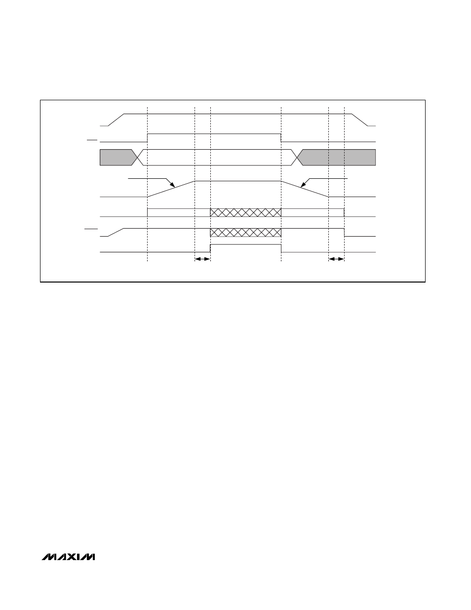
FORCED-PWM
FORCED-PWM
VID (D0-D4)
V
CORE
VROK
INVALID
CODE
INVALID
CODE
INTERNAL
PWM CONTROL
DRSKP
V
CC
SOFT-START
1/4
TH
SLEW RATE SET BY R
TIME
SOFT-SHUTDOWN
1/4
TH
SLEW RATE SET BY R
TIME
SHDN
t
BLANK
20s typ
t
BLANK
20s typ
Figure
8. Power-Up and Shutdown Sequence Timing Diagram
the negative output-voltage excursion. When the con-
troller reaches the 0V target, the drivers are disabled
(DRSKP driven low and PWM_ outputs pulled low), the
reference turns off, and the supply current drops to
about 10µA (max). When a fault condition—output
UVLO or thermal shutdown—activates the shutdown
sequence, the protection circuitry sets the fault latch to
prevent the controller from restarting. To clear the fault
latch and reactivate the controller, toggle SHDN or
cycle V
CC
power below 1V.
Fault Protection
Output Overvoltage Protection (Unlatched)
The overvoltage-protection (OVP) circuit is designed to
protect the CPU against a shorted high-side MOSFET
by drawing high current and blowing the battery fuse.
The MAX8707 continuously monitors the output for an
overvoltage fault. The controller detects an OVP fault if
the output voltage exceeds the set target voltage by
more than 200mV. After entering pulse-skipping opera-
tion (SKIP rising edge), the OVP threshold is set to
1.75V until the output voltage drops below the target
voltage for the first time. Once the MAX8707 detects
the output is being regulated (V
OUT
≈ V
TARGET
), the
OVP threshold begins tracking the target voltage again.
When the OVP circuit detects an overvoltage fault, it
immediately enters forced-PWM operation—pulling
DRSKP high so the drivers force the low-side gate dri-
vers high (DL = V
DD
) and pull the high-side gate dri-
vers low (DH = LX). The controller does not initiate an
on-time pulse until the output voltage drops below the
OVP threshold. This action turns on the synchronous-
rectifier MOSFET with 100% duty and, in turn, rapidly
discharges the output filter capacitor and forces the
output low. If the condition that caused the overvoltage
(such as a shorted high-side MOSFET) persists, the
battery fuse blows.
Overvoltage protection can be disabled through the no-
fault test mode (see the No-Fault Test Mode section).
Output Undervoltage Protection (Latched)
The output undervoltage-protection (UVP) function is
similar to foldback current limiting, but employs a timer
rather than a variable current limit. If the MAX8707 out-
put voltage is under 70% of the nominal value, the con-
troller activates the shutdown sequence and sets the
fault latch. Once the controller ramps down to the 0V
setting, it forces the PWM_ driver outputs low. Toggle
SHDN or cycle the V
CC
power supply below 1V to clear
the fault latch and reactivate the controller.
UVP can be disabled through the no-fault test mode
(see the No-Fault Test Mode section).
Thermal Fault Protection (Latched)
The MAX8707 features a thermal fault-protection circuit.
When the junction temperature rises above +160
°C, a