Pin description – Rainbow Electronics MAX8707 User Manual
Page 13
MAX8707
Multiphase, Fixed-Frequency Controller for
AMD Hammer CPU Core Power Supplies
______________________________________________________________________________________
13
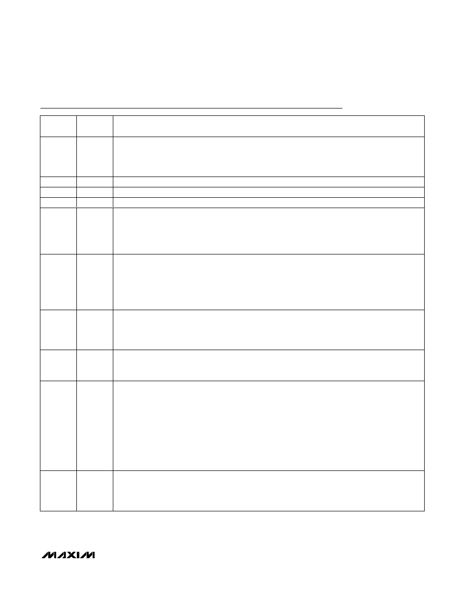
Pin Description
PIN
NAME
FUNCTION
1
D2
Low-Voltage VID DAC Code Input. The D0–D4 inputs do not have internal pullups. These 1.0V logic inputs
are designed to interface directly with the CPU. In normal mode (Table 4, SUS = GND), the output voltage
is set by the VID code indicated by the logic-level voltages on D0–D4. In suspend mode (SUS = high), the
output voltage tracks the voltage at SUSV.
2
D3
Low-Voltage VID DAC Code Input
3
D4
Low-Voltage VID DAC Code Input (MSB)
4
N.C.
No Connect. Leave open. Pin internally connected.
5
SKIP
Pulse-Skipping Indicator Input. When pulse skipping, the controller blanks the VROK upper threshold.
3.3V or V
CC
(high) = 1-phase pulse-skipping operation (phases 2, 3, and 4 disabled)
GND = multiphase forced-PWM operation
The controller automatically enters forced-PWM mode during startup, shutdown, and the no-CPU VID
mode.
6
SHDN
Shutdown Control Input. This input cannot withstand the battery voltage. Connect to V
CC
for normal
operation. Connect to ground to put the IC into its 50nA (typ) shutdown state. During the startup and
shutdown transitions, the output voltage is ramped at 1/4th the output-voltage slew rate programmed by
R
TIME
. After completing soft-shutdown, the drivers are disabled—DRSKP and PWM_ are pulled low.
Forcing SHDN to 11V~13V disables both overvoltage-protection and undervoltage-protection circuits, and
clears the fault latch. Do not connect SHDN to >13V.
7
SUS
Suspend Control Input. When the controller detects a transition on SUS, the controller slews the output
voltage to the new voltage level determined by SUSV (SUS = high) or D0–D4 (SUS = low). The controller
blanks VROK during the transition and another 20µs after the new target voltage is reached. When SUS is
high, the offset (OFS) is automatically disabled.
8
SUSV
Suspend-Mode Voltage Input. Connect to the output of a resistive voltage-divider from REF to GND to
provide an analog voltage between 0.4V to 2V. The output voltage is set by the voltage at SUSV when SUS
is high.
9
ILIM(AVE)
Average Current-Limit Threshold Adjustment. The controller uses the accurate CRSP-to-CRSN current-
sense voltage to limit the average current per phase. When the average current-limit threshold is
exceeded, the controller internally reduces the peak inductor current-limit threshold (ILIM(PK))
at 2% of
I
PKLIMIT
per µs until the average current remains within the programmed limits. When the accurate current
sensing is disabled (CRSP = V
CC
), the average current-limit circuit is disabled and I
LIM(AVE)
should be
connected to V
CC
.
The average current-limit threshold defaults to 25mV if ILIM(AVE)
is connected to V
CC
. In adjustable mode,
the average current-limit threshold voltage is precisely 1/20th the voltage difference between ILIM(AVE)
and the reference: (V
REF
- V
ILIM(AVE)
) / 20 for a range of 1.0V (V
REF
- 1V) to 1.8V (V
REF
- 0.2V). The logic
threshold for switchover to the 25mV default value is approximately V
CC
- 1V.
10
OFS
Adjustable Offset Voltage Input. For 0 < V
OFS
< 0.8V, 1/8th the voltage at OFS is subtracted from the
output. For 1.2V < V
OFS
< 2.0V, 1/8th the difference between REF and OFS is added to the output.
Voltages in the range of 0.8V < V
OFS
< 1.2V are undefined. The controller disables the offset amplifier
during suspend mode (SUS = high).